

Question: Part 1: Seven-Segment Indicator The seven-segment indicator (see Figure 1) can be used to display any one of the decimal digits 0 through 9. For
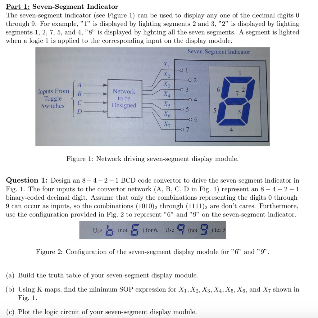
Part 1: Seven-Segment Indicator The seven-segment indicator (see Figure 1) can be used to display any one of the decimal digits 0 through 9. For example, " 1" is displayed by lighting segments 2 and 3, "2" is displayed by lighting segments 1, 2, 7, 5, and 4, "8" is displayed by lighting all the seven segments. A segment is lighted when a logic 1 is applied to the corresponding input on the display module. Seven-Segment Indicator Inputs From Toggle Switches Network to be Designed 4 Figure 1: Network driving seven-segment display module. Question 1: Design an 8- 4-2-1 BCD code convertor to drive the seven-segment indicator in Fig. 1. The four inputs to the convertor network (A, B, C, D in Fig. 1) represent an 8-4-2-1 binary-coded decimal digit. Assume that only the combinations representing the digits 0 through 9 can occur as inputs, so the combinations (1010)2 through (1111)2 are don't cares. Furthermore, use the configuration provided in Fig. 2 to represent "6" and "9" on the seven-segment indicator. Use(not)for 6. Use not) for 9 Figure 2: Configuration of the seven-segment display module for "6" and "9" (a) Build the truth table of your seven-segment display module (b) Using K-maps, find the minimum SOP expression for Xi, X2, X3, X4, X5, X6, and X7 shown in Fig. 1. (c) Plot the logic circuit of your seven-segment display module. Part 1: Seven-Segment Indicator The seven-segment indicator (see Figure 1) can be used to display any one of the decimal digits 0 through 9. For example, " 1" is displayed by lighting segments 2 and 3, "2" is displayed by lighting segments 1, 2, 7, 5, and 4, "8" is displayed by lighting all the seven segments. A segment is lighted when a logic 1 is applied to the corresponding input on the display module. Seven-Segment Indicator Inputs From Toggle Switches Network to be Designed 4 Figure 1: Network driving seven-segment display module. Question 1: Design an 8- 4-2-1 BCD code convertor to drive the seven-segment indicator in Fig. 1. The four inputs to the convertor network (A, B, C, D in Fig. 1) represent an 8-4-2-1 binary-coded decimal digit. Assume that only the combinations representing the digits 0 through 9 can occur as inputs, so the combinations (1010)2 through (1111)2 are don't cares. Furthermore, use the configuration provided in Fig. 2 to represent "6" and "9" on the seven-segment indicator. Use(not)for 6. Use not) for 9 Figure 2: Configuration of the seven-segment display module for "6" and "9" (a) Build the truth table of your seven-segment display module (b) Using K-maps, find the minimum SOP expression for Xi, X2, X3, X4, X5, X6, and X7 shown in Fig. 1. (c) Plot the logic circuit of your seven-segment display module
Step by Step Solution
There are 3 Steps involved in it

Get step-by-step solutions from verified subject matter experts