

Question: Part 2 - Digital to Analog Converter ( DAC ) In this part of the project, you will build a 4 - bit digital to
Part Digital to Analog Converter DAC
In this part of the project, you will build a bit digital to analog converter DAC
You must investigate DACs that are available in Literature. You should discuss at least different DAC. You will design an RR Ladder DAC.
Propose the schematic of a bit RR Ladder DAC.
Do a comprehensive theoretical analysis of the circuit. DETERMINE THE vtext out as functions of the bit values.
Implement it in LTSpice.
Implement it in a physical circuit.
Do necessary measurements to completely validate the circuit and the desired behavior.
Feed the output of the ADC in the text st part as the input of the DAC. Discuss the results.
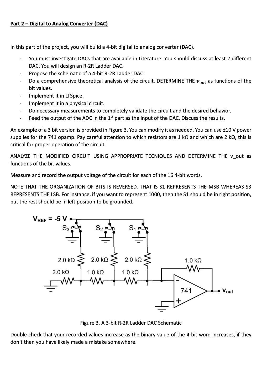
An example of a bit version is provided in Figure You can modify it as needed. You can use pm mathrm~V power supplies for the opamp. Pay careful attention to which resistors are mathrmkOmega and which are mathrmkOmega this is critical for proper operation of the circuit.
ANALYZE THE MODIFIED CIRCUIT USING APPROPRIATE TECNIQUES AND DETERMINE THE vout as functions of the bit values.
Measure and record the output voltage of the circuit for each of the bit words.
NOTE THAT THE ORGANIZATION OF BITS IS REVERSED. THAT IS S REPRESENTS THE MSB WHEREAS S REPRESENTS THE LSB For instance, if you want to represent then the S should be in right position, but the rest should be in left position to be grounded.
Figure A bit RR Ladder DAC Schematic
Double check that your recorded values increase as the binary value of the bit word increases, if they don't then you have likely made a mistake somewhere.
Step by Step Solution
There are 3 Steps involved in it
1 Expert Approved Answer
Step: 1 Unlock

Question Has Been Solved by an Expert!
Get step-by-step solutions from verified subject matter experts
Step: 2 Unlock
Step: 3 Unlock