

Question: PART 2 : Inverting Summing Amplifier For the inverting summing amplifier circuit of Figure 3 . 2 , a ) Derive the output equation, Vo
PART : Inverting Summing Amplifier
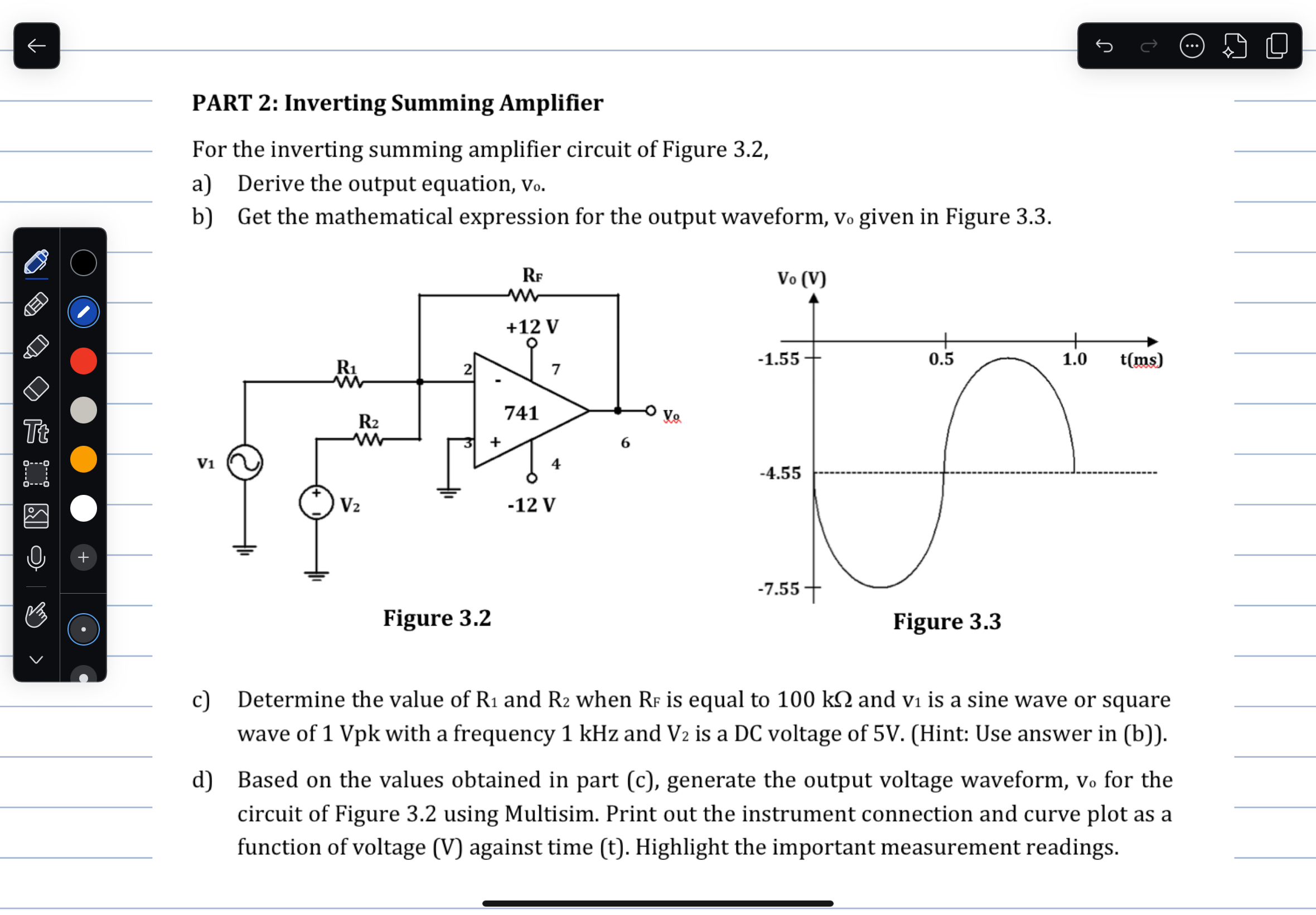
For the inverting summing amplifier circuit of Figure
a Derive the output equation, Vo
b Get the mathematical expression for the output waveform, vo given in Figure
c Determine the value of and when is equal to and is a sine wave or square wave of Vpk with a frequency kHz and is a DC voltage of V Hint: Use answer in b
d Based on the values obtained in part c generate the output voltage waveform, vo for the circuit of Figure using Multisim. Print out the instrument connection and curve plot as a function of voltage against time Highlight the important measurement readings.
Step by Step Solution
There are 3 Steps involved in it
1 Expert Approved Answer
Step: 1 Unlock

Question Has Been Solved by an Expert!
Get step-by-step solutions from verified subject matter experts
Step: 2 Unlock
Step: 3 Unlock