

Question: Part B: Frequency Response In this lab, you will also be guided to design a lead and then a lag compensator for improving the transient
Part B: Frequency Response
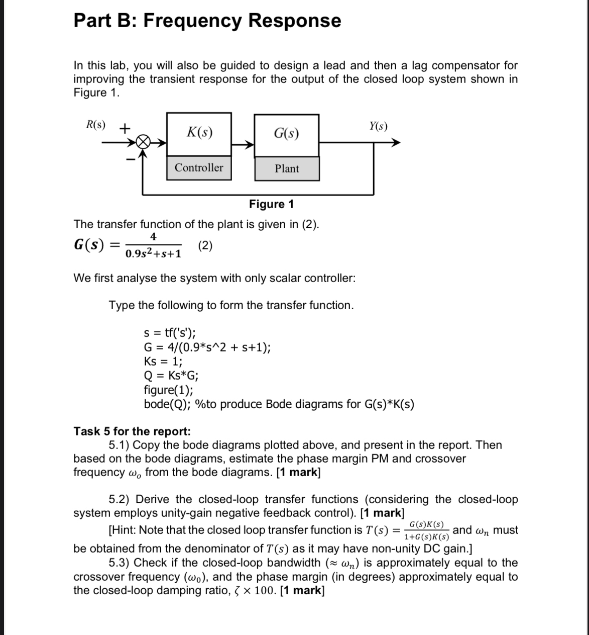
In this lab, you will also be guided to design a lead and then a lag compensator for improving the transient response for the output of the closed loop system shown in Figure
The transfer function of the plant is given in
We first analyse the system with only scalar controller:
Type the following to form the transfer function.
;
;
;
;
figure;
bode; produce Bode diagrams for
Task for the report:
Copy the bode diagrams plotted above, and present in the report. Then based on the bode diagrams, estimate the phase margin PM and crossover frequency from the bode diagrams.
Derive the closedloop transfer functions considering the closedloop system employs unitygain negative feedback control mark
Hint: Note that the closed loop transfer function is and must be obtained from the denominator of as it may have nonunity DC gain.
Check if the closedloop bandwidth ~~ is approximately equal to the crossover frequency and the phase margin in degrees approximately equal to the closedloop damping ratio,
Step by Step Solution
There are 3 Steps involved in it
1 Expert Approved Answer
Step: 1 Unlock

Question Has Been Solved by an Expert!
Get step-by-step solutions from verified subject matter experts
Step: 2 Unlock
Step: 3 Unlock