

Question: PART II - RC Time Constants 1 . Construct the circuit shown below. The input is a ( 5 0 % )
PART IIRC Time Constants
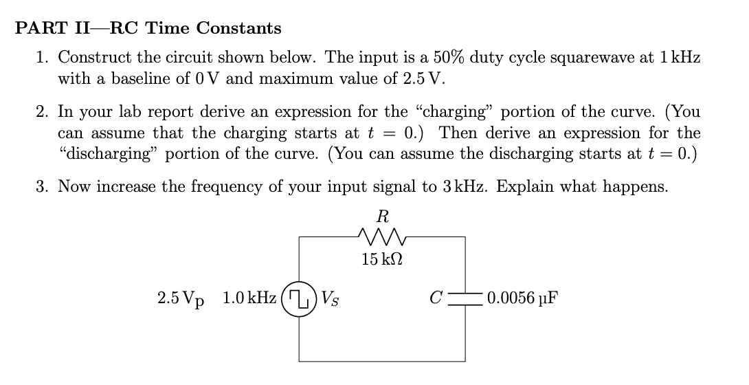
Construct the circuit shown below. The input is a duty cycle squarewave at kHz with a baseline of V and maximum value of V
In your lab report derive an expression for the "charging" portion of the curve. You can assume that the charging starts at t Then derive an expression for the "discharging" portion of the curve. You can assume the discharging starts at t
Now increase the frequency of your input signal to kHz Explain what happens.
Step by Step Solution
There are 3 Steps involved in it
1 Expert Approved Answer
Step: 1 Unlock

Question Has Been Solved by an Expert!
Get step-by-step solutions from verified subject matter experts
Step: 2 Unlock
Step: 3 Unlock