

Question: perform the below tasks using the picture below as a knowledge base The visual aid above will help you to perform the tasks mentioned directly
perform the below tasks using the picture below as a knowledge base
 The visual aid above will help you to perform the tasks mentioned directly below:
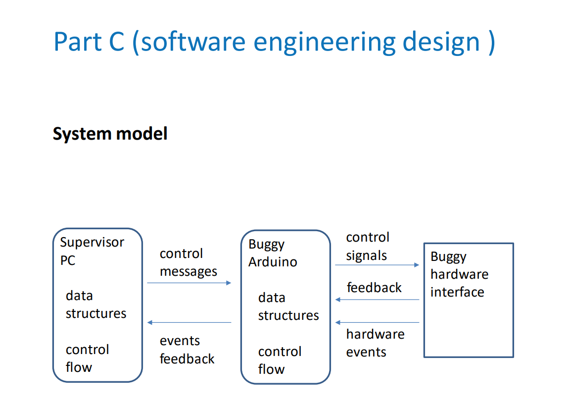
specify the messages, signals, events and feedback between the components and the buggy hardware interface.
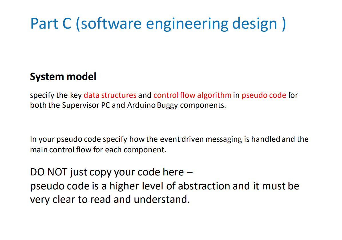
specify the key data structures and control flow algorithm in pseudo code for both the Supervisor PC and Arduino Buggy components.
Arduino code: shown below is the arduino code implemented:
#include
#define IR_SENSOR_RIGHT 2
#define IR_SENSOR_LEFT 3
#define MOTOR_SPEED 150
const int US_TRIG=15;
const int US_ECHO=14;
const int MAX_DIST=15;
//Right motor
int RightMotor=9;
int rightMotorPin1=5;
int rightMotorPin2=6;
//Left motor
int LeftMotor=10;
int leftMotorPin1=8;
int leftMotorPin2=7;
//WAP - NAMES
char ssid[] = "Y2BUGGY";
char pass[] = "Y2PASSWORD";
WiFiServer server(80);
int Buggy; //switch statement
char c; // for if statement
bool wasdetected = false;// for object seen/cleared
bool detected = false;
void setup()
{
Serial.begin(9600); // WAP - SERVER SIDE SETUP
WiFi.beginAP(ssid, pass);
IPAddress ip = WiFi.localIP();
Serial.print("IP Address:");
Serial.println(ip);//prints ip address
server.begin();
pinMode(US_TRIG, OUTPUT);
pinMode(US_ECHO, INPUT);
pinMode(RightMotor, OUTPUT);
pinMode(rightMotorPin1, OUTPUT);
pinMode(rightMotorPin2, OUTPUT);
pinMode(LeftMotor, OUTPUT);
pinMode(leftMotorPin1, OUTPUT);
pinMode(leftMotorPin2, OUTPUT);
pinMode(IR_SENSOR_RIGHT, INPUT);
pinMode(IR_SENSOR_LEFT, INPUT);
rotateMotor(0,0);
}
void loop() {
int IRSensorValueR = digitalRead(IR_SENSOR_RIGHT);
int IRSensorValueL = digitalRead(IR_SENSOR_LEFT);
int distance = readUltrasonic(US_ECHO); // put your main code here, to run repeatedly:
WiFiClient client = server.available();
if (client.connected()){
//Serial.println("Client connected");
//}
c = client.read();
//serial.println(c);
if( c == '1' ){
Buggy = 1;
}
else if(c == '2'){
Buggy = 2;
}
}
switch (Buggy)
{
case 1: //start buggy
if (distance
if (detected == false){
rotateMotor(0, 0);
server.write(distance);
Serial.println(distance);
wasdetected = true;
detected = true;
}
}
else{
detected = false;
if (detected == false && wasdetected == true){
server.write(200);
wasdetected = false;
}
if (IRSensorValueR == HIGH && IRSensorValueL == HIGH)
{
rotateMotor(MOTOR_SPEED, MOTOR_SPEED);
}
else if (IRSensorValueR == LOW && IRSensorValueL == HIGH )
{
rotateMotor(-MOTOR_SPEED, MOTOR_SPEED);
}
else if (IRSensorValueR == HIGH && IRSensorValueL == LOW )
{
rotateMotor(MOTOR_SPEED, -MOTOR_SPEED);
}
else
{
rotateMotor(0, 0);
}
}
break;
case 2: //buggy off
rotateMotor(0,0);
break;
}
}
void rotateMotor(int rightMotorSpeed, int leftMotorSpeed)
{
if (rightMotorSpeed
{
digitalWrite(rightMotorPin1,LOW);
digitalWrite(rightMotorPin2,HIGH);
}
else if (rightMotorSpeed > 0)
{
digitalWrite(rightMotorPin1,HIGH);
digitalWrite(rightMotorPin2,LOW);
}
else
{
digitalWrite(rightMotorPin1,LOW);
digitalWrite(rightMotorPin2,LOW);
}
if (leftMotorSpeed
{
digitalWrite(leftMotorPin1,LOW);
digitalWrite(leftMotorPin2,HIGH);
}
else if (leftMotorSpeed > 0)
{
digitalWrite(leftMotorPin1,HIGH);
digitalWrite(leftMotorPin2,LOW);
}
else
{
digitalWrite(leftMotorPin1,LOW);
digitalWrite(leftMotorPin2,LOW);
}
analogWrite(RightMotor, abs(rightMotorSpeed));
analogWrite(LeftMotor, abs(leftMotorSpeed));
}
long readUltrasonic(int US_ECHO){
long duration, cm;
digitalWrite(US_TRIG, LOW);
delayMicroseconds(2);
digitalWrite(US_TRIG, HIGH);
delayMicroseconds(10);
digitalWrite(US_TRIG, LOW);
duration = pulseIn(US_ECHO, HIGH);
return duration / 29 /2;
}
Processing code:
import controlP5.*; //library
//import processing.serial.*; //library
import processing.net.*;
ControlP5 cp5;//create ControlP5 object
Client client;
float data;
PFont font; //do not change
boolean wasdetected = false;
void setup() { //same as arduino program
size(300, 300); //window size, (width, height)
client = new Client(this, "192.168.4.1", 80);//connected arduino port
cp5 = new ControlP5(this); //do not change
font = createFont("Georgia Bold", 20); //font for buttons and title
cp5.addButton("ON") /ame of button
.setPosition(95, 50) //x and y upper left corner of button
.setSize(120, 70) //(width, height)
.setFont(font) //font
.setColorBackground(color(255, 0, 0)) //background r,g,b
.setColorForeground(color(0, 255, 0)) //mouse over color r,g,b
.setColorLabel(color(0, 0, 0)) //text color r,g,b
;
cp5.addButton("OFF")
.setPosition(95, 150)
.setSize(120, 70)
.setFont(font)
.setColorBackground(color(255, 0, 0))
.setColorForeground(color(0, 255, 0))
.setColorLabel(color(0, 0, 0))
;
}
void draw() {
background(0, 0, 0); // background color of window (r, g, b)
data = client.read();
if (data != -1){
//if (wasdetected == false){
println("Obstruction seen");
//println(data);
delay(4000);
// wasdetected = true;
}
}
void ON() {
client.write("1");
}
void OFF() {
client.write("2");
}
Part C (software engineering design ) System model Part C (software engineering design ) System model specify the key data structures and control flow algorithm in pseudo code for both the Supervisor PC and Arduino Buggy components. In your pseudo code specify how the event driven messaging is handled and the main control flow for each component. DO NOT just copy your code here - pseudo code is a higher level of abstraction and it must be very clear to read and understand
Step by Step Solution
There are 3 Steps involved in it

Get step-by-step solutions from verified subject matter experts