

Question: In the epicyclic gear train shown in Fig.15.35, the arm A, carrying the compound wheels D and E, turns freely on the output shaft.
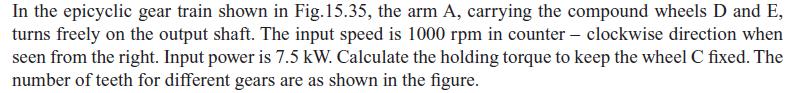
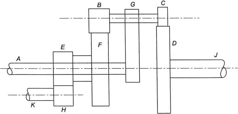
In the epicyclic gear train shown in Fig.15.35, the arm A, carrying the compound wheels D and E, turns freely on the output shaft. The input speed is 1000 rpm in counter-clockwise direction when seen from the right. Input power is 7.5 kW. Calculate the holding torque to keep the wheel C fixed. The number of teeth for different gears are as shown in the figure. A E K H B G C F D
Step by Step Solution
3.39 Rating (155 Votes )
There are 3 Steps involved in it
Using the epicyclic gear train shown in Fig 1535 we can calculate the holding ... View full answer

Get step-by-step solutions from verified subject matter experts
Document Format (2 attachments)
6641c48bb3dc2_989045.pdf
180 KBs PDF File
6641c48bb3dc2_989045.docx
120 KBs Word File