

Question: PHYZOZL Name Lab #5 - Exploring Simple AC Circuits You will be using a prototype HEEL simulator to explore some aspects of the behavior of
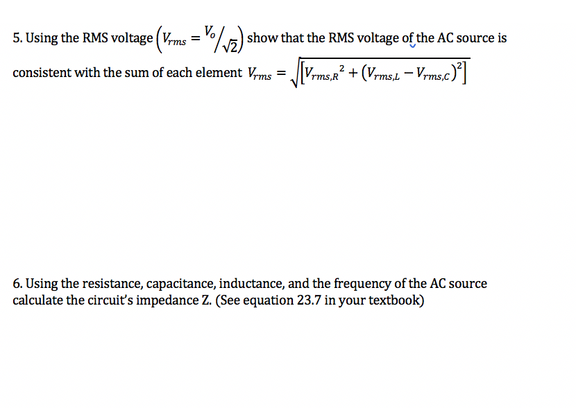
PHYZOZL Name Lab #5 - Exploring Simple AC Circuits You will be using a prototype HEEL simulator to explore some aspects of the behavior of basic AC circuits. After this exercise you should have a clearer understanding of how resistance, capacitance, inductance, and voltage frequency impact the behavior of basic LC and RLC circuits. Note: 1. You can fill in this report and append any required images, tables, etc. to create your assignment submission. 2. Calculations appearing in your report MUST include units. Failure to include them will result in reduced credit Part 1 An LC Circuit 1. Start the simulation with the link appearing above and choose the RLC workspace. Be sure to use the conventional current option during the exercise. Create a circuit with a battery and a capacitor in series to charge the capacitor. Click the capacitor and note its capacitance below. 2. Press Pause at the bottom of the screen and disconnect the battery and remove it from the simulation. 3. Connect an inductor in series with the capacitor. Click the inductor and write down its inductance below. 4-. Press the Piayarrow. Record your observations below. 5. Click the Current Chart device and place the sensor on the wire between the capacitor and inductor. Adjust the yaxis scale so that you can see the full sinusoidal curve and maximum current; note the maximum/minimum current, and determine the currents period (time between successive positive or negative peaks). 6. Using the inductance and capacitance values you write down calculate the circuit' s t l f = 1 . resonan angu ar requency mo QE Covert the period you measured in #5 to an angular frequency to = 211 / Period. How do (on and to relate? 6. Click Voltage Chart and place the detectors on either side of the capacitor. Add a valaneter on both sides of the inductor. Make sure the polarity of the detectors is consistent, meaning at any instant the current direction between black and red probes is the same for both. Adjust the yaxis using the +/ arrows so that you can see the full sinusoidal curve and maximum voltage on the chart Record the qualitative similarities and differences between the curves. What are the maximum and minimum voltages? Determine and report the circuit's period (time between successive maximum or minimum peaks). 7. Take a screenshot of your LC circuit and include it in your lab report. C Copyright Trident Technical College, 2021. All rights reserved.Pal'tZ-RLCCIrcult 1. Create a circuit with an AC Voltage source in series with a resistor, inductor, and capacitor. Record the resistance. Set the capacitance to 0.1F and the inductance to 5.0H. 2. Click the AC voltage source element; set the voltage to 120V. Set its frequency to 1 Hz. 3. Using a single Voltage Chart device and two voltmeters (the max number of devices the prototype simulation supports concurrently) probe each element in the circuit, including the AC Voltage source. Make sure the polarity is consistent across the measuring devices. 4-. Record the maximum and minimum voltages on each element. Take sufficient time to observe and qualitatively describe the similarities and differences in the voltage behavior across groups of circuit elements. Record your observations and answers to the questions that follow. Which circuit element(s) have inphase voltage with the AC source? Which circuit e1 ement(s) have outof phase voltage with one another, and by what degree (90, 180, etc)? 5. Using the RMS voltage (Vrms = / vz show that the RMS voltage of the AC source is consistent with the sum of each element Vrms = rms,R + (Vrms,L - Vrms.c)2 6. Using the resistance, capacitance, inductance, and the frequency of the AC source calculate the circuit's impedance Z. (See equation 23.7 in your textbook)7. Measure the circuit current as it leaves the AC source using a Current Chart device or Ammeter. Record the maximum value of the current. Using the RMS current, show that the RMS voltage from the AC source is consistent with the RMS current and impedance. @ Copyright Trident Technical College, 2021. All rights reserved. 8. Change the frequency of the AC source to the circuit's resonant frequency (as close as you can get to it). Allow the simulation to run for one minute to adjust. Repeat steps #4, 6 and 7. What similarities and differences do you see between the two rounds of measurements
Step by Step Solution
There are 3 Steps involved in it

Get step-by-step solutions from verified subject matter experts