

Question: Plant Instrumentation & Control Figure 3.1 provides the schematic description of a salt mixing tank. An aqueous salt solution enters the tank at a flow
Plant Instrumentation & Control
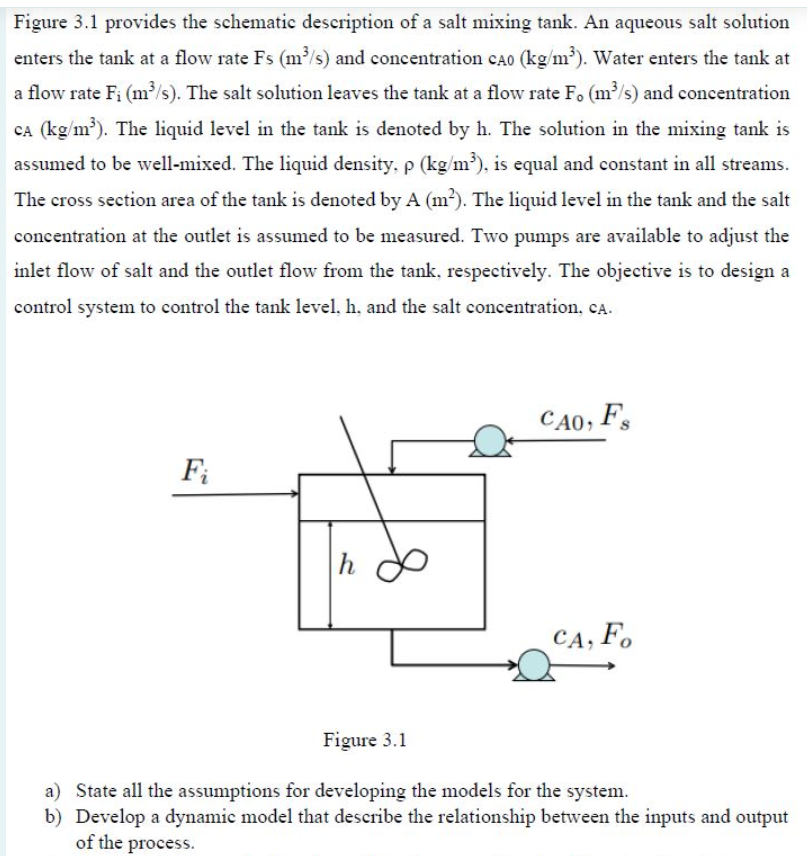
Figure 3.1 provides the schematic description of a salt mixing tank. An aqueous salt solution enters the tank at a flow rate Fs (ms) and concentration cao (kg/m?). Water enters the tank at a flow rate Fi (m?s). The salt solution leaves the tank at a flow rate F. (m?s) and concentration CA (kg/m). The liquid level in the tank is denoted by h. The solution in the mixing tank is assumed to be well-mixed. The liquid density, p (kg/m), is equal and constant in all streams. The cross section area of the tank is denoted by A (m). The liquid level in the tank and the salt concentration at the outlet is assumed to be measured. Two pumps are available to adjust the inlet flow of salt and the outlet flow from the tank, respectively. The objective is to design a control system to control the tank level, h, and the salt concentration, ca. CA0, F. Fi h CA, F. Figure 3.1 a) State all the assumptions for developing the models for the system. b) Develop a dynamic model that describe the relationship between the inputs and output of the process
Step by Step Solution
There are 3 Steps involved in it

Get step-by-step solutions from verified subject matter experts