

Question: PLC pump ladder diagram problem Question 4b and c please 4. Suppose you need to control a test station via a Programmable Logic Controller (PLC).
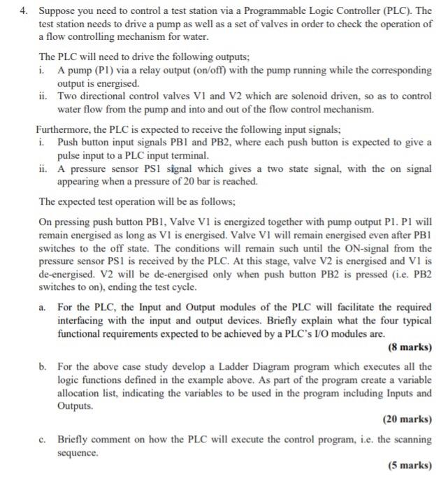
4. Suppose you need to control a test station via a Programmable Logic Controller (PLC). The test station needs to drive a pump as well as a set of valves in order to check the operation of a flow controlling mechanism for water. The PLC will need to drive the following outputs; i. A pump (Pl) via a relay output (on/off) with the pump running while the corresponding output is energised. ii. Two directional control valves VI and V2 which are solenoid driven, so as to control water flow from the pump and into and out of the flow control mechanism. Furthermore, the PLC is expected to receive the following input signals; i. Push button input signals PB1 and PB2, where each push button is expected to give a pulse input to a PLC input terminal. ii. A pressure sensor PS1 signal which gives a two state signal, with the on signal appearing when a pressure of 20 bar is reached. The expected test operation will be as follows; On pressing push button PB1, Valve VI is energized together with pump output Pl. Pl will remain energised as long as VI is energised. Valve VI will remain energised even after PBI switches to the off state. The conditions will remain such until the ON-signal from the pressure sensor PS1 is received by the PLC. At this stage, valve V2 is energised and VI is de-energised. V2 will be de-energised only when push button PB2 is pressed (i.e. PB2 switches to on), ending the test cycle. a. For the PLC, the Input and Output modules of the PLC will facilitate the required interfacing with the input and output devices. Briefly explain what the four typical functional requirements expected to be achieved by a PLC's 10 modules are. (8 marks) b. For the above case study develop a Ladder Diagram program which executes all the logic functions defined in the example above. As part of the program create a variable allocation list, indicating the variables to be used in the program including Inputs and Outputs. (20 marks) c. Briefly comment on how the PLC will execute the control program, i.e. the scanning sequence
Step by Step Solution
There are 3 Steps involved in it

Get step-by-step solutions from verified subject matter experts