

Question: Please answer 5th question briefly ...1 12:56 burse Outline ment 1 S LTE 1 Amrita School of Engineering, Coimbatore Overall Rating: of 1 15ECE303 Linear
Please answer 5th question briefly
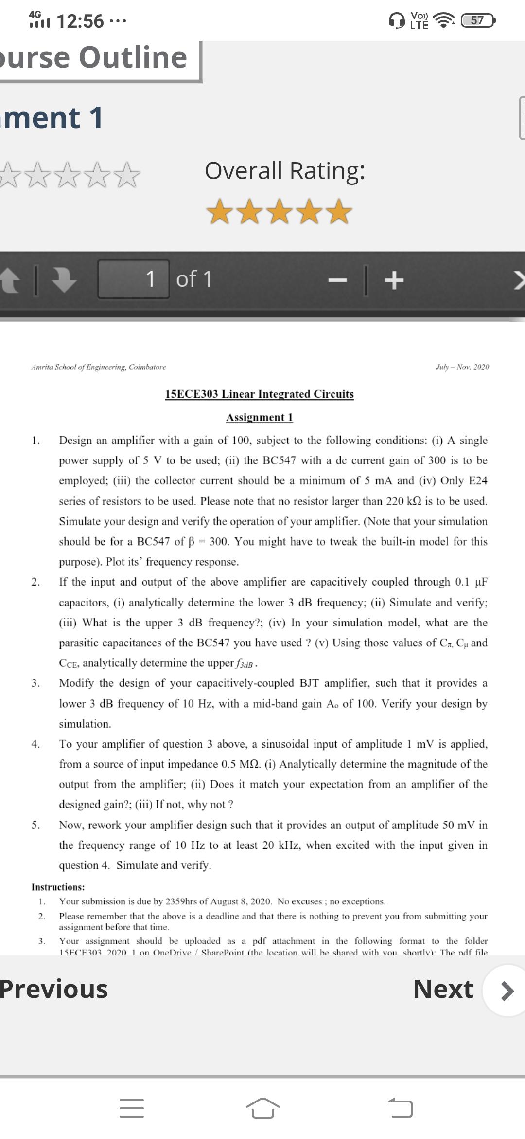
...1 12:56 burse Outline ment 1 S LTE 1 Amrita School of Engineering, Coimbatore Overall Rating: of 1 15ECE303 Linear Intecrated Circuits Assignment 1 July Nov. 2020 I. 2. 3. 4. 5. Design an amplifier with a gain of 100, subject to the following conditions: (i) A single power supply of 5 V to be used; (ii) the BC547 with a dc current gain of 300 is to be employed; (iii) the collector current should be a minimum of 5 mA and (iv) Only E24 series of resistors to be used. Please note that no resistor larger than 220 kQ is to be used. Simulate your design and verify the operation of your amplifier. (Note that your simulation should be for a BC547 of = 300. You might have to tweak the built-in model for this purpose). Plot its' frequency response. If the input and output of the above amplifier are capacitively coupled through 0.1 gF capacitors, (i) analytically determine the lower 3 dB frequency; (ii) Simulate and verify; (iii) What is the upper 3 dB frequency?; (iv) In your simulation model, what are the parasitic capacitances of the BC547 you have used ? (v) Using those values of Cp and CCE, analytically determine the upperf3dB. Modify the design of your capacitively-coupled BJT amplifier, such that it provides a lower 3 dB frequency of 10 Hz, with a mid-band gain Ao of 100. Verify your design by simulation. To your amplifier of question 3 above, a sinusoidal input of amplitude I mV is applied, from a source of input impedance 0.5 MQ. (i) Analytically determine the magnitude of the output from the amplifier; (ii) Does it match your expectation from an amplifier of the designed gain?; (iii) If not, why not ? Now, rework your amplifier design such that it provides an output of amplitude 50 mV in the frequency range of 10 Hz to at least 20 kHz, when excited with the input given in question 4. Simulate and verify. Instructions: 2. 3. Your submission is due by 2359hrs of August 8, 2020. No excuses ; no exceptions. Please remember that the above is a deadline and that there is nothing to prevent you flom submitting your assignment before that time. Your assignment should be uploaded as a pdf attachment in the following format to the folder I / Will With Previous Next >
Step by Step Solution
3.43 Rating (162 Votes )
There are 3 Steps involved in it
Amplifiers and filters are widely used electronic circuits that have the properties of both amplific... View full answer

Get step-by-step solutions from verified subject matter experts