

Question: PLEASE ANSWER THIS QUESTION ALSO PLEASE SHOW ME A CLEAR MULTISIM RESULT. THANKS 6. You will use a seven segment decoder and a common-anode BCD-to-Seven-Segment-Decoder
PLEASE ANSWER THIS QUESTION ALSO PLEASE SHOW ME A CLEAR MULTISIM RESULT. THANKS
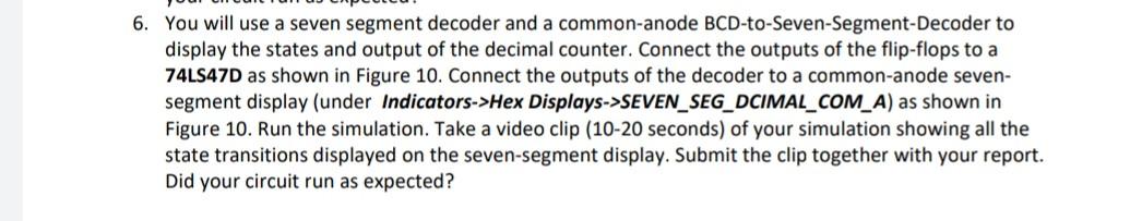
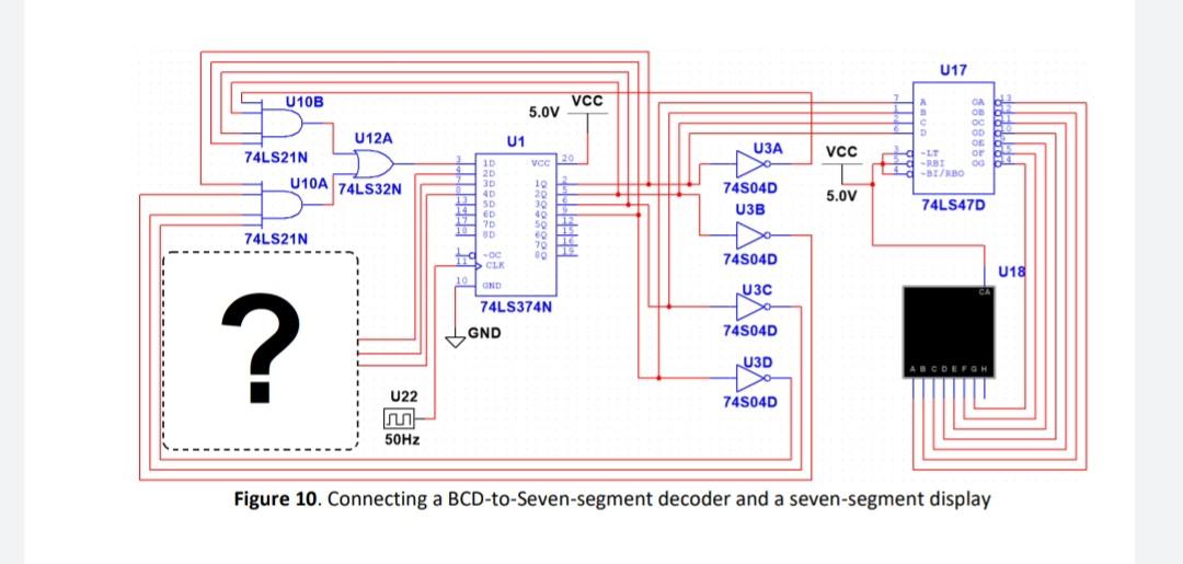
6. You will use a seven segment decoder and a common-anode BCD-to-Seven-Segment-Decoder to display the states and output of the decimal counter. Connect the outputs of the flip-flops to a 74LS47D as shown in Figure 10. Connect the outputs of the decoder to a common-anode seven- segment display (under Indicators->Hex Displays->SEVEN_SEG_DCIMAL_COM_A) as shown in Figure 10. Run the simulation. Take a video clip (10-20 seconds) of your simulation showing all the state transitions displayed on the seven-segment display. Submit the clip together with your report. Did your circuit run as expected? U17 U10B VCC 5.0V U12A U1 GA - OBO oc OD OG D OF - O -BT/BO U3A VCC VOC 20 74LS21N U10A 74LS32N 10 20 30 ar SD ED ?D 745040 U3B 5.0V 74LS470 10 3 20 30 40 50 1 70 LIE 12 DC 1 74LS21N d-00 CLK 74504D U18 10 UND U3C 74LS374N GND 74504D ? U3D EFGH U22 74504D 50Hz Figure 10. Connecting a BCD-to-Seven-segment decoder and a seven-segment display
Step by Step Solution
There are 3 Steps involved in it

Get step-by-step solutions from verified subject matter experts