

Question: please answer this thanks! The shaft below is for a helical gear shaft. Please keep your solution as a template The shaft system. Note that
please answer this thanks! The shaft below is for a helical gear shaft. Please keep your solution as a template The shaft system.
Note that the forces on FBD must be at the true direction to ensure correct T V and M diagrams
c
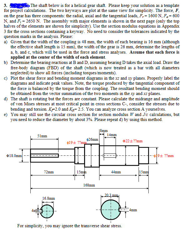
for project calculations. The two keyways are plot at the same view for simplicity. The force,
on the gear has three components: the radial, axial and the tangential loads,
N and The assembly with major elements is shown in the next page only the top
halves of the elements are shown for simplicity Use the section modulus equations in Appendix
for the cross sections containing a keyway. No need to consider the tolerances indicated by the
question marks in the analysis. Please:
a Given that the width of the coupling is mm the width of each bearing is mm although
the effective shaft length is mm the width of the gear is mm determine the lengths of
and c which will be used in the force and stress analyses. Assume that each force is
applied at the center of the width of each element.
b Determine the bearing reactions at B and D assuming bearing D takes the axial load. Draw the
freebody diagram FBD of the shaft which is now treated as a bar with all diameters
neglected to show all forces including torquesmoments
c Plot the shear force and bending moment diagrams in the and planes. Properly label the
diagrams and indicate peak values. Note, the torque produced by the tangential component of
the force is balanced by the torque from the coupling. The resultant bending moment should
be obtained from the vector summation of the two moments in the and planes.
d The shaft is rotating but the forces are constant. Please calculate the midrange and amplitude
of von Mises stresses at most critical point in cross sections C consider the stresses due to
bending and torsion. and You can analyze cross section A yourselves.
e You may still use the circular cross section for section modulus and calculations, but
you need to reduce the diameter by about Please repeat d by using this method.
For simplicity, you may ignore the transverse shear stress.
Step by Step Solution
There are 3 Steps involved in it
1 Expert Approved Answer
Step: 1 Unlock

Question Has Been Solved by an Expert!
Get step-by-step solutions from verified subject matter experts
Step: 2 Unlock
Step: 3 Unlock