

Question: Please, can you help me answer questions 1,2, and 3? I posted the mentioned example too. Thank you! A second country road (going south) now
Please, can you help me answer questions 1,2, and 3? I posted the mentioned example too. Thank you!
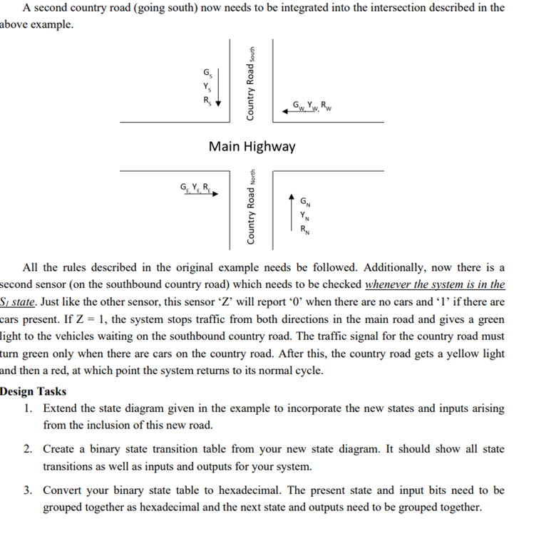
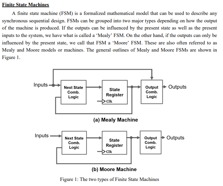
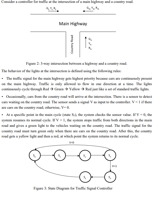
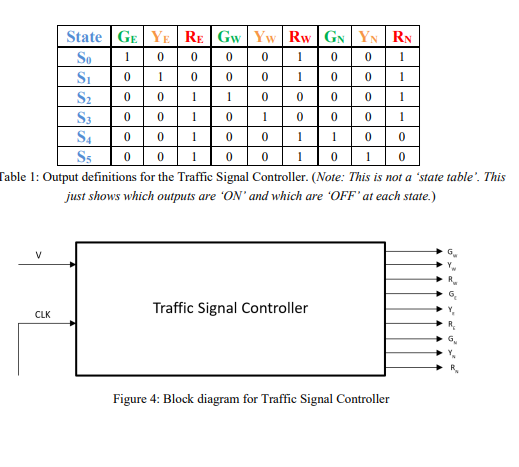
A second country road (going south) now needs to be integrated into the intersection described in the bove example. All the rules described in the original example needs be followed. Additionally, now there is a econd sensor (on the southbound country road) which needs to be checked whenever the system is in the State. Just like the other sensor, this sensor ' Z ' will report ' 0 ' when there are no cars and ' 1 ' if there are ars present. If Z=1, the system stops traffic from both directions in the main road and gives a green ight to the vehicles waiting on the southbound country road. The traffic signal for the country road must urn green only when there are cars on the country road. After this, the country road gets a yellow light and then a red, at which point the system returns to its normal cycle. Design Tasks 1. Extend the state diagram given in the example to incorporate the new states and inputs arising from the inclusion of this new road. 2. Create a binary state transition table from your new state diagram. It should show all state transitions as well as inputs and outputs for your system. 3. Convert your binary state table to hexadecimal. The present state and input bits need to be grouped together as hexadecimal and the next state and outputs need to be grouped together. Finite State Machines A finite state machine (FSM) is a formalized mathematical model that can be used to describe any synchronous sequential design. FSMs can be grouped into two major types depending on how the output of the machine is produced. If the outputs can be influenced by the present state as well as the present inputs to the system, we have what is called a 'Mealy' FSM. On the other hand, if the outputs can only be influenced by the present state, we call that FSM a 'Moore' FSM. These are also often referred to as Mealy and Moore models or machines. The general outlines of Mealy and Moore FSMs are shown in Figure 1. (a) Mealy Machine (b) Moore Machine Figure 1: The two types of Finite State Machines Figure 2: 3-way intersection between a highway and a country road. The behavior of the lights at the intersection is defined using the following rules: - The traffic signal for the main highway gets highest priority because cars are continuously present on the main highway. Traffic is only allowed to flow in one direction at a time. The lights continuously cycle through Red Green Yellow Red just like a set of standard traffic lights. - Occasionally, cars from the country road will arrive at the intersection. There is a sensor to detect cars waiting on the country road. The sensor sends a signal V as input to the controller. V=1 if there are cars on the country road; otherwise, V=0. - At a specific point in the main cycle (state S3 ), the system checks the sensor value. If V=0, the system resumes its normal cycle. If V=1, the system stops traffic from both directions in the main road and gives a green light to the vehicles waiting on the country road. The traffic signal for the country road must turn green only when there are cars on the country road. After this, the country road gets a yellow light and then a red, at which point the system returns to its normal cycle. Figure 3: State Diagram for Traffic Signal Controller 'able 1: Output definitions for the Traffic Signal Controller. (Note: This is not a 'state table'. This just shows which outputs are ' ON and which are 'OFF' at each state.) Figure 4: Block diagram for Traffic Signal Controller A second country road (going south) now needs to be integrated into the intersection described in the bove example. All the rules described in the original example needs be followed. Additionally, now there is a econd sensor (on the southbound country road) which needs to be checked whenever the system is in the State. Just like the other sensor, this sensor ' Z ' will report ' 0 ' when there are no cars and ' 1 ' if there are ars present. If Z=1, the system stops traffic from both directions in the main road and gives a green ight to the vehicles waiting on the southbound country road. The traffic signal for the country road must urn green only when there are cars on the country road. After this, the country road gets a yellow light and then a red, at which point the system returns to its normal cycle. Design Tasks 1. Extend the state diagram given in the example to incorporate the new states and inputs arising from the inclusion of this new road. 2. Create a binary state transition table from your new state diagram. It should show all state transitions as well as inputs and outputs for your system. 3. Convert your binary state table to hexadecimal. The present state and input bits need to be grouped together as hexadecimal and the next state and outputs need to be grouped together. Finite State Machines A finite state machine (FSM) is a formalized mathematical model that can be used to describe any synchronous sequential design. FSMs can be grouped into two major types depending on how the output of the machine is produced. If the outputs can be influenced by the present state as well as the present inputs to the system, we have what is called a 'Mealy' FSM. On the other hand, if the outputs can only be influenced by the present state, we call that FSM a 'Moore' FSM. These are also often referred to as Mealy and Moore models or machines. The general outlines of Mealy and Moore FSMs are shown in Figure 1. (a) Mealy Machine (b) Moore Machine Figure 1: The two types of Finite State Machines Figure 2: 3-way intersection between a highway and a country road. The behavior of the lights at the intersection is defined using the following rules: - The traffic signal for the main highway gets highest priority because cars are continuously present on the main highway. Traffic is only allowed to flow in one direction at a time. The lights continuously cycle through Red Green Yellow Red just like a set of standard traffic lights. - Occasionally, cars from the country road will arrive at the intersection. There is a sensor to detect cars waiting on the country road. The sensor sends a signal V as input to the controller. V=1 if there are cars on the country road; otherwise, V=0. - At a specific point in the main cycle (state S3 ), the system checks the sensor value. If V=0, the system resumes its normal cycle. If V=1, the system stops traffic from both directions in the main road and gives a green light to the vehicles waiting on the country road. The traffic signal for the country road must turn green only when there are cars on the country road. After this, the country road gets a yellow light and then a red, at which point the system returns to its normal cycle. Figure 3: State Diagram for Traffic Signal Controller 'able 1: Output definitions for the Traffic Signal Controller. (Note: This is not a 'state table'. This just shows which outputs are ' ON and which are 'OFF' at each state.) Figure 4: Block diagram for Traffic Signal Controller
Step by Step Solution
There are 3 Steps involved in it

Get step-by-step solutions from verified subject matter experts