

Question: Please complete the content (my id is 16) A DC motor is a common actuator in control system. The input to this device is a
 Please complete the content (my id is 16)
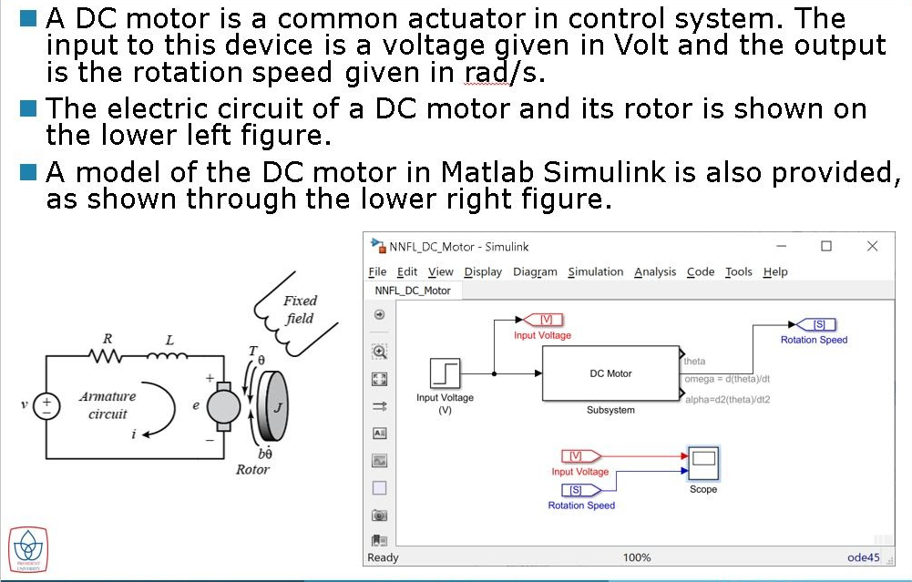
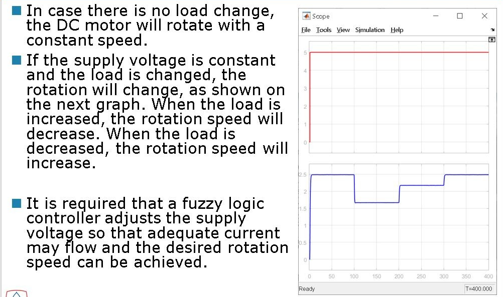
A DC motor is a common actuator in control system. The input to this device is a voltage given in Volt and the output is the rotation speed given in rad/s. The electric circuit of a DC motor and its rotor is shown on the lower left figure. A model of the DC motor in Matlab Simulink is also provided, as shown through the lower right figure. X NNFL_DC_Motor - Simulink File Edit View Display Diagram Simulation Analysis Code Tools Help NNFL_DC_Motor Fixed field [S] Rotation Speed R Input Voltage DC Motor theta omega = d(thetadt Armature circuit Input Voltage (V) alpha=d2(theta)/dt2 Subsystem Rotor Input Voltage IISI Rotation Speed Scope Ready 100% ode45 - X Scope File Tools View Simulation Help 4 In case there is no load change, the DC motor will rotate with a constant speed. If the supply voltage is constant and the load is changed, the rotation will change, as shown on the next graph. When the load is increased, the rotation speed will decrease. When the load is decreased, the rotation speed will increase. 2 2 1 It is required that a fuzzy logic controller adjusts the supply voltage so that adequate current may flow and the desired rotation speed can be achieved. 0 0 50 100 150 200 250 300 350 400 Ready T=400.000 Design a fuzzy logic control that will maintain the motor to rotate with the velocity of Your-Student- M ID/10 rad/s. Fuzzy Logic Controller Screenshot of *.slx Screenshots of membership functions, rules, and rule viewer. *.slx and *.fis files. A DC motor is a common actuator in control system. The input to this device is a voltage given in Volt and the output is the rotation speed given in rad/s. The electric circuit of a DC motor and its rotor is shown on the lower left figure. A model of the DC motor in Matlab Simulink is also provided, as shown through the lower right figure. X NNFL_DC_Motor - Simulink File Edit View Display Diagram Simulation Analysis Code Tools Help NNFL_DC_Motor Fixed field [S] Rotation Speed R Input Voltage DC Motor theta omega = d(thetadt Armature circuit Input Voltage (V) alpha=d2(theta)/dt2 Subsystem Rotor Input Voltage IISI Rotation Speed Scope Ready 100% ode45 - X Scope File Tools View Simulation Help 4 In case there is no load change, the DC motor will rotate with a constant speed. If the supply voltage is constant and the load is changed, the rotation will change, as shown on the next graph. When the load is increased, the rotation speed will decrease. When the load is decreased, the rotation speed will increase. 2 2 1 It is required that a fuzzy logic controller adjusts the supply voltage so that adequate current may flow and the desired rotation speed can be achieved. 0 0 50 100 150 200 250 300 350 400 Ready T=400.000 Design a fuzzy logic control that will maintain the motor to rotate with the velocity of Your-Student- M ID/10 rad/s. Fuzzy Logic Controller Screenshot of *.slx Screenshots of membership functions, rules, and rule viewer. *.slx and *.fis files
Step by Step Solution
There are 3 Steps involved in it

Get step-by-step solutions from verified subject matter experts