

Question: Please complete the control module in Verilog. In this project, you are asked to implement in Verilog the control logic of a simple electronic kitchen
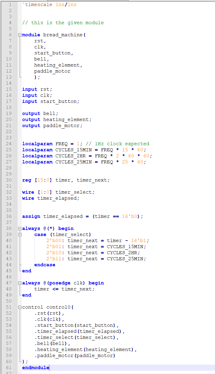
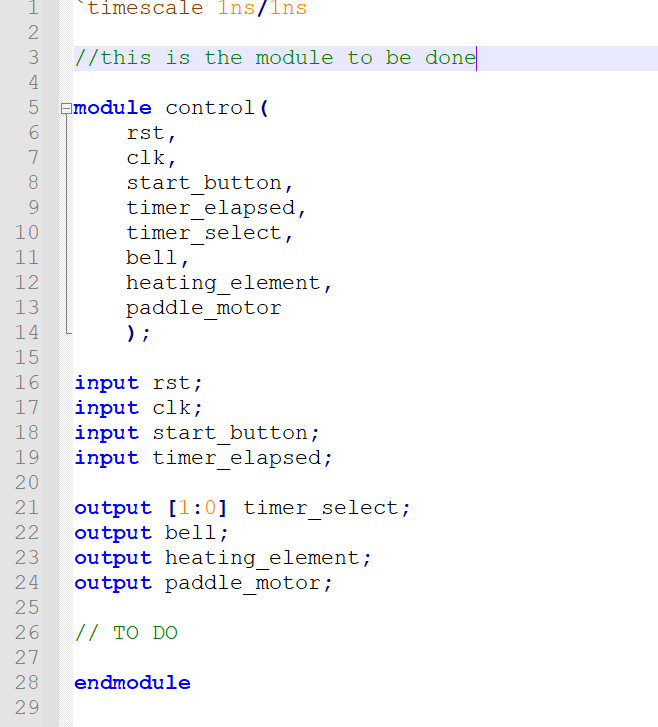
Please complete the control module in Verilog.
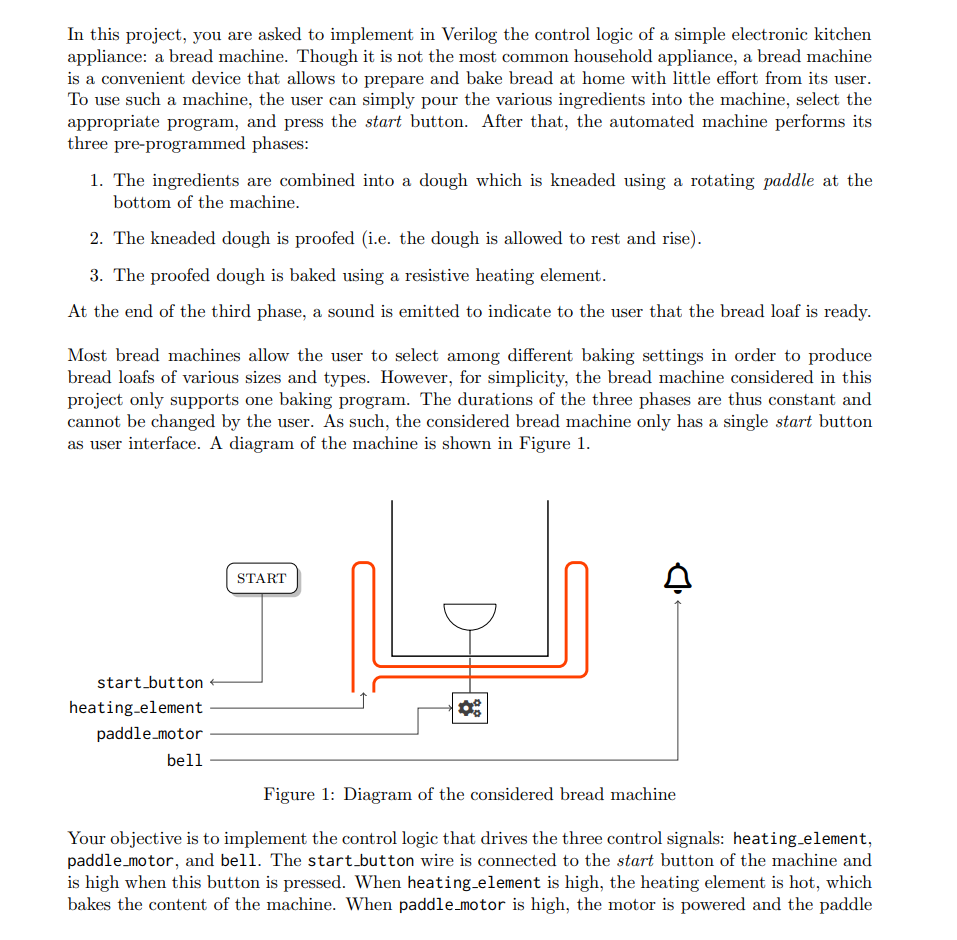
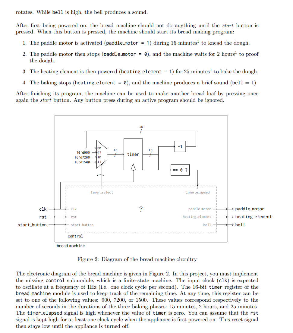
In this project, you are asked to implement in Verilog the control logic of a simple electronic kitchen appliance: a bread machine. Though it is not the most common household appliance, a bread machine is a convenient device that allows to prepare and bake bread at home with little effort from its user. To use such a machine, the user can simply pour the various ingredients into the machine, select the appropriate program, and press the start button. After that, the automated machine performs its three pre-programmed phases: 1. The ingredients are combined into a dough which is kneaded using a rotating paddle at the bottom of the machine. 2. The kneaded dough is proofed i.e. the dough is allowed to rest and rise). 3. The proofed dough is baked using a resistive heating element. At the end of the third phase, a sound is emitted to indicate to the user that the bread loaf is ready. Most bread machines allow the user to select among different baking settings in order to produce bread loafs of various sizes and types. However, for simplicity, the bread machine considered in this project only supports one baking program. The durations of the three phases are thus constant and cannot be changed by the user. As such, the considered bread machine only has a single start button as user interface. A diagram of the machine is shown in Figure 1. START start_button heating element paddle_motor bell Figure 1: Diagram of the considered bread machine Your objective is to implement the control logic that drives the three control signals: heating element, paddle_motor, and bell. The start button wire is connected to the start button of the machine and is high when this button is pressed. When heating element is high, the heating element is hot, which bakes the content of the machine. When paddle_motor is high, the motor is powered and the paddle rotates. While bell is high, the bell produces a sound. After first being powered on, the bread machine should not do anything until the start button is pressed. When this button is pressed, the machine should start its bread making program: 1. The paddle motor is activated (paddle_motor = 1) during 15 minutes to knead the dough. 2. The paddle motor then stops (paddle_motor = 0), and the machine waits for 2 hours to proof the dough. 3. The heating element is then powered (heating element = 1) for 25 minutes to bake the dough. 4. The baking stops (heating element = 0), and the machine produces a brief sound (bell = 1). After finishing its program, the machine can be used to make another bread loaf by pressing once again the start button. Any button press during an active program should be ignored. -1 16 16 timer 16'd900 -01 16'd7200 10 16'd1500 O ? timer-select timer.elapsed clk clk ? paddle_motor paddle_motor heating element rst rst heating element start button start_button bell bell control bread machine Figure 2: Diagram of the bread machine circuitry The electronic diagram of the bread machine is given in Figure 2. In this project, you must implement the missing control submodule, which is a finite-state machine. The input clock (clk) is expected to oscillate at a frequency of 1Hz (i.e. one clock cycle per second). The 16-bit timer register of the bread_machine module is used to keep track of the remaining time. At any time, this register can be set to one of the following values: 900, 7200, or 1500. These values correspond respectively to the number of seconds in the durations of the three baking phases: 15 minutes, 2 hours, and 25 minutes. The timer elapsed signal is high whenever the value of timer is zero. You can assume that the rst signal is kept high for at least one clock cycle when the appliance is first powered on. This reset signal then stays low until the appliance is turned off. "timescale Ins/ins 1 2 3 4 5 // this is the given module 6 Emodule bread_machine rst, clk, start_button, bell, heating_element, paddle_motor input rst; input clk; input start_button; output bell; output heating element; output paddle_motor; localparam FREQ = 1; // 1Hz clock expected localparam CYCLES 15MIN = FREQ * 60; localparam CYCLES_2HR = FREQ 2 * 60 * 60; localparam CYCLES_25MIN = FREQ 25 60; reg [15:0] timer, timer_next; wire [1:0] timer_select; wire timer_elapsed; 7 8 9 10 11 12 13 14 15 16 17 18 19 20 21 22 23 24 25 26 27 28 29 30 31 32 33 34 35 36 37 38 39 40 41 42 43 44 45 46 47 48 49 50 51 52 53 54 55 56 57 58 59 60 61 assign timer_elapsed = (timer == 16'b0); always @ (*) begin case (timer_select) 2'600: timer_next = timer - 16'bl; 2'b01: timer_next = CYCLES_15MIN; 2'b10: timer_next = CYCLES_2HR; 2'b11: timer next = CYCLES 25MIN; case -end always @ (posedge clk) begin timer
Step by Step Solution
There are 3 Steps involved in it

Get step-by-step solutions from verified subject matter experts