

Question: Please complete this circuit where the truth table should look like this but it is not the x = 0 y = 0 and z
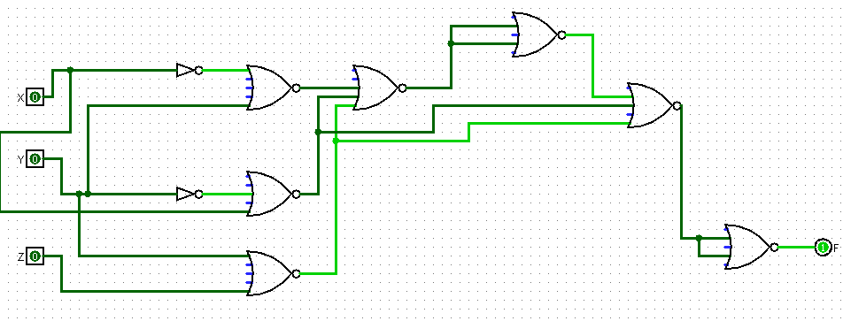
Please complete this circuit where the truth table should look like this but it is not the x y and z inputs should equal but it is zero in this case. All other input outputs are the same. make sure to show the newly corrected drawing to its entirety. Only use NOR and inverter gates for the solution!!
Truth table:
X Y Z F
Expected Output:
And the second truth table with the correction mentioned where the output for x y z is instead of :
X Y Z F
Step by Step Solution
There are 3 Steps involved in it
1 Expert Approved Answer
Step: 1 Unlock

Question Has Been Solved by an Expert!
Get step-by-step solutions from verified subject matter experts
Step: 2 Unlock
Step: 3 Unlock