

Question: Please demonstrate how to use the PLECS simulation software to design a PD controller for the following buck - boost converter. Use PLECS simulation software
Please demonstrate how to use the PLECS simulation software to design a PD controller for the following buckboost converter.
Use PLECS simulation software to create the bode plot of the Gvd controltooutput transfer functionfor the BuckBoost converter described below.
Use the following parameters:
aInput Voltage V
bOutput Voltage V
cSwitching Frequency kHz
dInductance H
eResistance in series with inductance m
fInput Capacitance F
gOutput Capacitance F
hResistance in series with input capacitance m
iResistance in series with output capacitance m
jMOSFET with body diode drain to source on resistance m
kLoad current: iA iiA
Change Output Voltage VUse PLECS to create the bode plot of the Gvd controltooutput transfer functionfor the BuckBoost converter.
Design a Proportional Derivative compensator transfer function for the BuckBoost converter described by the bode plots of the Gvd controltooutput transfer functionsabove
Meet the following requirements:
aCrossover frequency at kHz
bPhase margin at
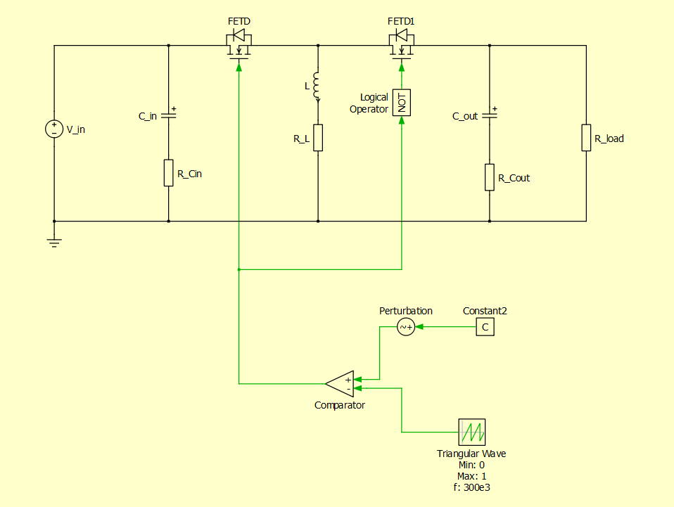
The construction of the base buckboost converter circuit in the software should look as follows:
Step by Step Solution
There are 3 Steps involved in it
1 Expert Approved Answer
Step: 1 Unlock

Question Has Been Solved by an Expert!
Get step-by-step solutions from verified subject matter experts
Step: 2 Unlock
Step: 3 Unlock