

Question: Please design a 2 - stage logic micro - operations circuit using J - K flip - flops using the imaged logic operations. Include a
Please design a stage logic microoperations circuit using JK flipflops using the imaged logic operations. Include a drawing of the circuit, including all work done to derive the circuit, including any relevant tables and k maps.
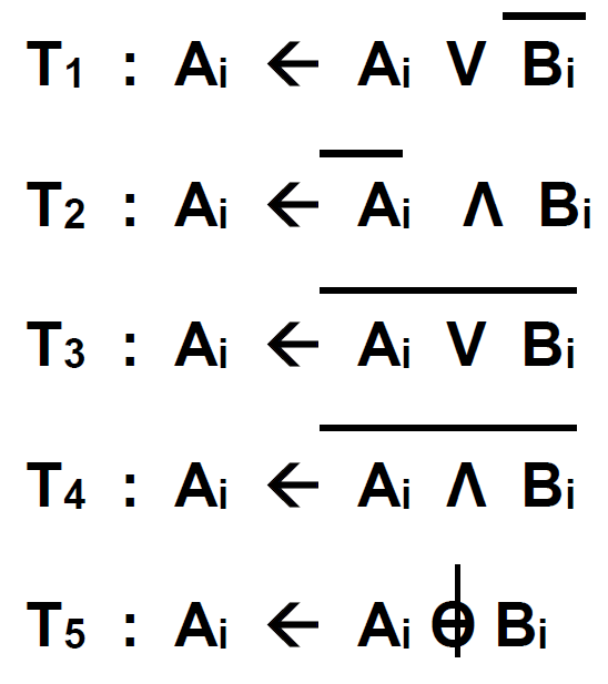
The first microoperation, Ai Ai V Bi is a nameless microoperation the boolean function Fxy
The second microoperation, Ai AiLambda Bi is a nameless microoperation, with the boolean function Fxy
The third microoperation, Ai Ai V Bi is the NOR microoperation, with the boolean fuction Fxy
The fourth microoperation, Ai Ai Lambda Bi the NAND microoperation, with the boolean function Fxy
The fifth microoperation, Ai Ai Bi is the XOR microoperation, with the boolean function F X Y
The fifth microoperation, XOR, can be implementedwired by connecting input pins Bi and another input pin into the inputs of an AND, and connecting the output of the AND into both J and K inputs of a JK flipflop, connecting the output Q into output bit Ai A clock pin goes into the clock input of the JK flipflop. I am not sure how the other microoperations are wired.
The flipflop state table for XOR is as follows
PS INPUT NEXT STATE FF INPUTS
Ai Bi Ai JAi KAi
x
x
x
x
The appropiate kmaps for XOR would be as follows
AiBi
xx
JAiBi
AiBi
xx
KAiBi
Such tables and kmaps for all microoperations are required. Please refer to a truth table and excitation table of the JK flipflop if needed.
For the twostage circuit, create one circuit with input B and output A and another circuit with input B and output A Both will have a common set of T inputs. I believe the circuit might use a single JK flipflop, but I am not certain.
Step by Step Solution
There are 3 Steps involved in it
1 Expert Approved Answer
Step: 1 Unlock

Question Has Been Solved by an Expert!
Get step-by-step solutions from verified subject matter experts
Step: 2 Unlock
Step: 3 Unlock