

Question: Please do not solve with codes. Solve with true tables gates etc. logic design project. Logic Design Project: Kitchen Timer Circuit Design Project Policies: Project
Please do not solve with codes. Solve with true tables gates etc. logic design project. Logic Design Project: Kitchen Timer Circuit Design
Project Policies: Project for EE must be done individually. Acceptable resources are your textbook, lecture notes, the EE website and specification sheets of used MSI chips. Other resources, human or not human, printed or online are prohibited. For the project you may also get a limited help from the research assistants.
Problem Statement: A kitchen timer is a device that allows a countdown timer to be set for a certain number of minutes and seconds, after which the device audibly alerts that the countdown is complete. For the minutes and seconds, the time is stored in two sets of FFs one that represents the tens digit and another the ones digit. The FFs count in binary from to or to in decimal for the ones digit and from to or to in decimal for the tens digit. The maximum storable value is minutes and seconds.
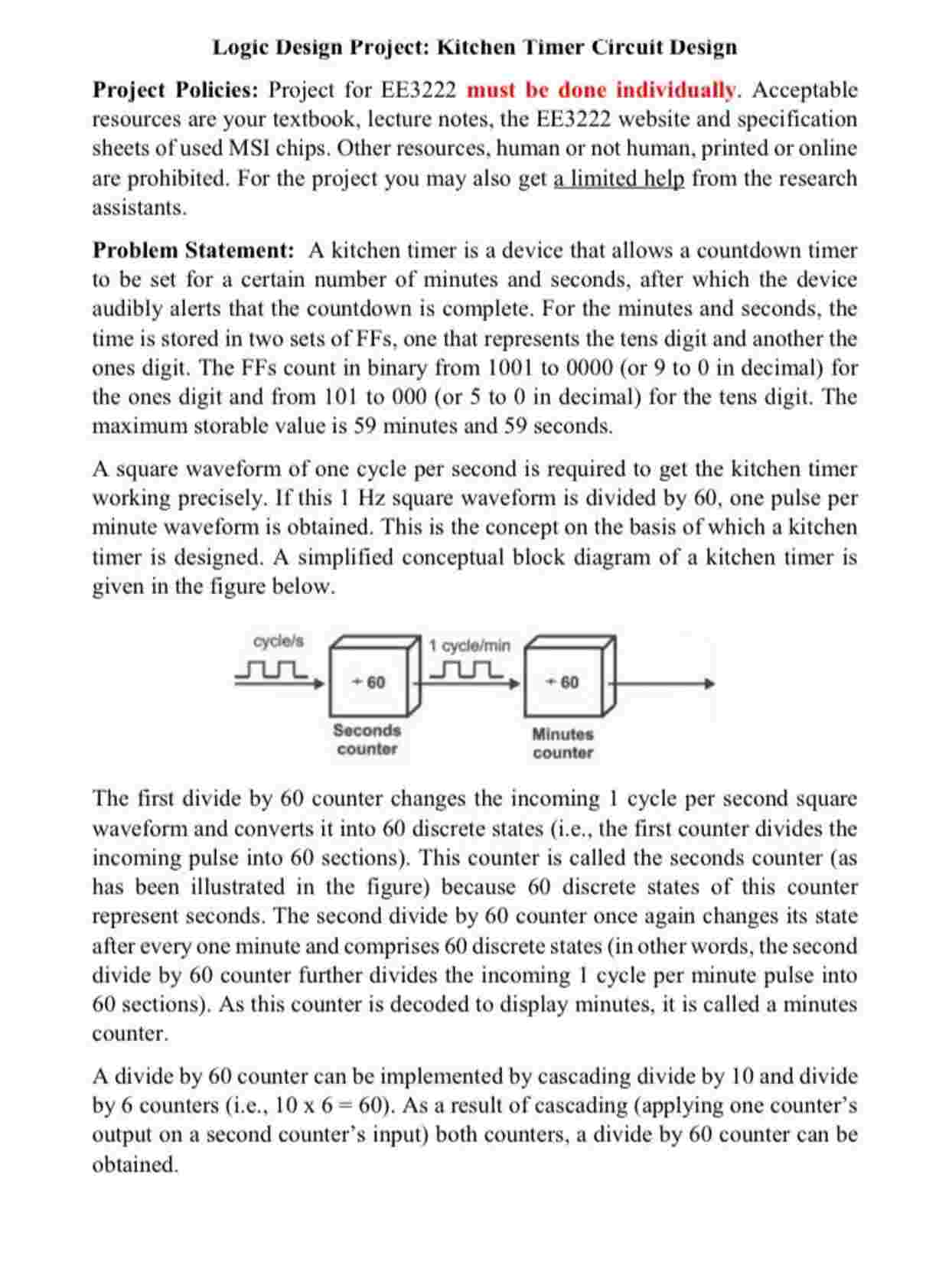
A square waveform of one cycle per second is required to get the kitchen timer working precisely. If this Hz square waveform is divided by one pulse per minute waveform is obtained. This is the concept on the basis of which a kitchen timer is designed. A simplified conceptual block diagram of a kitchen timer is given in the figure below.
The first divide by counter changes the incoming cycle per second square waveform and converts it into discrete states ie the first counter divides the incoming pulse into sections This counter is called the seconds counter as has been illustrated in the figure because discrete states of this counter represent seconds. The second divide by counter once again changes its state after every one minute and comprises discrete states in other words, the second divide by counter further divides the incoming cycle per minute pulse into sections As this counter is decoded to display minutes, it is called a minutes counter.
A divide by counter can be implemented by cascading divide by and divide by counters ietimes As a result of cascading applying one counter's output on a second counter's input both counters, a divide by counter can be obtained. Logic Design Project: Kitchen Timer Circuit Design
Project Policies: Project for EE must be done individually. Acceptable resources are your textbook, lecture notes, the EE website and specification sheets of used MSI chips. Other resources, human or not human, printed or online are prohibited. For the project you may also get a limited help from the research assistants.
Problem Statement: A kitchen timer is a device that allows a countdown timer to be set for a certain number of minutes and seconds, after which the device audibly alerts that the countdown is complete. For the minutes and seconds, the time is stored in two sets of FFs one that represents the tens digit and another the ones digit. The FFs count in binary from to or to in decimal for the ones digit and from to or to in decimal for the tens digit. The maximum storable value is minutes and seconds.
A square waveform of one cycle per second is required to get the kitchen timer working precisely. If this Hz square waveform is divided by one pulse per minute waveform is obtained. This is the concept on the basis of which a kitchen timer is designed. A simplified conceptual block diagram of a kitchen timer is given in the figure below.
The first divide by counter changes the incoming cycle per second square waveform and converts it into discrete states ie the first counter divides the incoming pulse into sections This counter is called the seconds counter as has been illustrated in the figure because discrete states of this counter represent seconds. The second divide by counter once again changes its state after every one minute and comprises discrete states in other words, the second divide by counter further divides the incoming cycle per minute pulse into sections As this counter is decoded to display minutes, it is called a minutes counter.
A divide by counter can be implemented by cascading divide by and divide by counters ietimes As a result of cascading applying one counter's output on a second counter's input both counters, a divide by counter can be obtained. Design a kitchen timer circuit by using synchronous counters, BCD to segment decoders, and segment displays. The designed kitchen timer circuit should satisfy the following requirements:
In the circuit, two synchronous counters need to be designed as building blocks: a divide by counter decade countdown counter and a divide by counter counter Also, it will be assumed that a Hz square waveform is available.
JK flipflops should be used to build the synchronous counters that count the minutes a The kitchen
Step by Step Solution
There are 3 Steps involved in it
1 Expert Approved Answer
Step: 1 Unlock

Question Has Been Solved by an Expert!
Get step-by-step solutions from verified subject matter experts
Step: 2 Unlock
Step: 3 Unlock