

Question: Please explain and provide the correct equation Consider using an HC9S12 in single-chip mode in an embedded system. Using the table below, and assuming the
Please explain and provide the correct equation
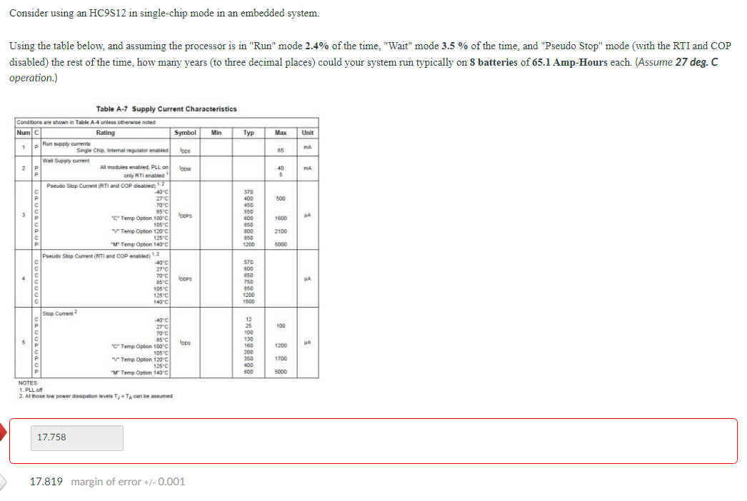
Consider using an HC9S12 in single-chip mode in an embedded system. Using the table below, and assuming the processor is in "Run" mode 2.4% of the time, "Wait" mode 3.5 % of the time, and "Pseudo Stop" mode (with the RTI and COP disabled) the rest of the time, how many years (to three decimal places) could your system run typically on 8 batteries of 65.1 Amp-Hours each. (Assume 27 deg. C operation.) Typ Max Unit 65 MA ma 40 5 500 370 400 450 550 550 600 650 800 850 1200 1800 2100 5000 Table A-7 Supply Current Characteristics Conditions are shown in Table A-4 unless otherwise noted Num cl Rating Symbol Min Run supply currents 1 Single Chip Internal regulator enabled toos Wall Supply current 2P All modules enabled, PLL on bow only RTI and Pseudo Stop Current (RTI and COP disabled)12 40C 27C 70C 3 85C FODPS *C* Temp Option 100C 105C Temp Option 120C 125C "Temp Option 140C Pseudo Stop Current (RTI and COP enabled) 1.2 40C 27C 4 C 70C lopps 85C 105C 125C 140C Stop Current 40C 27C 70C 5 85C lops *C Temp Option 100C 105C V Temp Option 120C 125C "ur Temp Option 140C NOTES 1. PLL 2. At those low power dissipation levels T3 - TA can be assumed HA VODOVOOOOOOOOOOOOOOOOOO " 570 600 650 750 850 1200 1500 100 12 25 100 130 160 200 350 400 600 1200 1700 5000 17.758 17.819 margin of error +/- 0.001 Consider using an HC9S12 in single-chip mode in an embedded system. Using the table below, and assuming the processor is in "Run" mode 2.4% of the time, "Wait" mode 3.5 % of the time, and "Pseudo Stop" mode (with the RTI and COP disabled) the rest of the time, how many years (to three decimal places) could your system run typically on 8 batteries of 65.1 Amp-Hours each. (Assume 27 deg. C operation.) Typ Max Unit 65 MA ma 40 5 500 370 400 450 550 550 600 650 800 850 1200 1800 2100 5000 Table A-7 Supply Current Characteristics Conditions are shown in Table A-4 unless otherwise noted Num cl Rating Symbol Min Run supply currents 1 Single Chip Internal regulator enabled toos Wall Supply current 2P All modules enabled, PLL on bow only RTI and Pseudo Stop Current (RTI and COP disabled)12 40C 27C 70C 3 85C FODPS *C* Temp Option 100C 105C Temp Option 120C 125C "Temp Option 140C Pseudo Stop Current (RTI and COP enabled) 1.2 40C 27C 4 C 70C lopps 85C 105C 125C 140C Stop Current 40C 27C 70C 5 85C lops *C Temp Option 100C 105C V Temp Option 120C 125C "ur Temp Option 140C NOTES 1. PLL 2. At those low power dissipation levels T3 - TA can be assumed HA VODOVOOOOOOOOOOOOOOOOOO " 570 600 650 750 850 1200 1500 100 12 25 100 130 160 200 350 400 600 1200 1700 5000 17.758 17.819 margin of error +/- 0.001
Step by Step Solution
There are 3 Steps involved in it

Get step-by-step solutions from verified subject matter experts