

Question: PLEASE HELP Communications Systems Using the TIMS 301 Lab Manual (available online too), Solve the following theoretical questions shown below. Homework to be solved in
PLEASE HELP
Communications Systems
Using the TIMS 301 Lab Manual (available online too), Solve the following theoretical questions shown below.
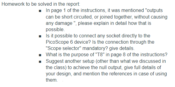
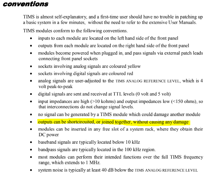

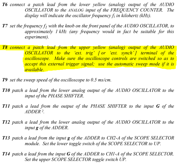
Homework to be solved in the report: In page 1 of the instructions, it was mentioned "outputs can be short circuited, or joined together, without causing any damage", please explain in detail how that is possible. Is it possible to connect any socket directly to the Pico Scope 6 device? Is the connection through the "Scope selector" mandatory? give details. What is the purpose of "T8" in page 8 of the instructions? Suggest another setup (other than what we discussed in the class) to achieve the null output, give full details of your design, and mention the references in case of using them. INTRODUCTION TO TIMS TIMS is a modular system for modelling telecommunications block diagrams. Since block diagrams themselves represent telecommunications systems, or sub-systems, and each sub-system can probably be represented by a mathematical equation, then TIMS can also be said to be a telecommunications equation modeller. Most TIMS modules perform a single function. For example, there are multipliers, adders, filters, samplers. Other modules generate signals such as sinewaves, square waves, random sequences. Complex systems are modelled by a collection of these simple modules. There are few modules that perform complex functions which otherwise could have been performed by a collection of simpler modules. conventions TIMS is almost self-explanatory, and a first-time user should have no trouble in patching up a basic system in a few minutes, without the need to refer to the extensive User Manuals. TIMS modules conform to the following conventions. inputs to each module are located on the left hand side of the front panel outputs from each module are located on the right hand side of the front panel modules become powered when plugged in, and pass signals via external patch leads connecting front panel sockets sockets involving analog signals are coloured yellow sockets involving digital signals are coloured red analog signals are user-adjusted to the TIMS ANALOG REFERENCE LEVEL, which is 4 volt peak-to-peak digital signals are sent and received at TTL levels (0 volt and 5 volt) input impedances are high (>10 kohms) and output impedances low (10 kohms) and output impedances low (
Step by Step Solution
There are 3 Steps involved in it

Get step-by-step solutions from verified subject matter experts