Question: Please help me with this. the second option is saying like portal to Registrate for classes. please draw a function flow block digram fir the
Please help me with this.
the second option is saying like portal to Registrate for classes.
please draw a function flow block digram fir the advising period.
there are more information in Wikipedia
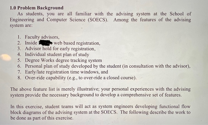
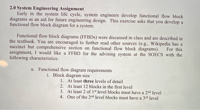
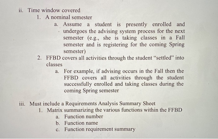
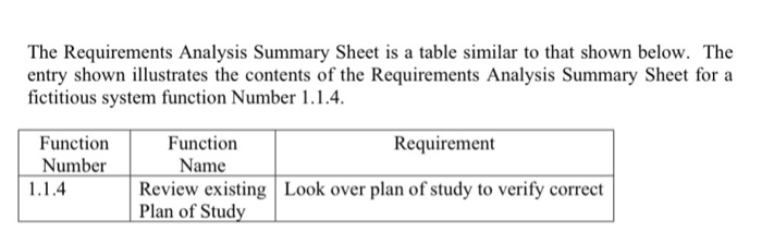
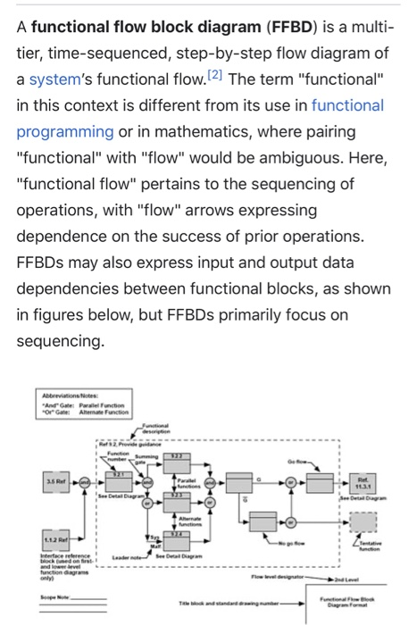
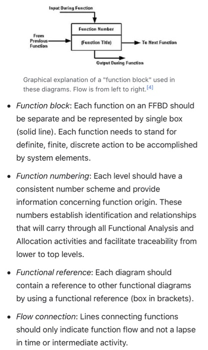
1.0 Problem Background As students, you are all familiar with the advising system at the School of Engineering and Computer Science (SOECS). Among the features of the advising system are: 1. Faculty advisors, 2. Inside web based registration, 3. Advisor hold for early registration, 4. Individual student plan of study 5. Degree Works degree tracking system 6. Personal plan of study developed by the student (in consultation with the advisor), 7. Early/late registration time windows, and 8. 'Over-ride capability (e.g., to over-ride a closed course). The above feature list is merely illustrative; your personal experiences with the advising system provide the necessary background to develop a comprehensive set of features. In this exercise, student teams will act as system engineers developing functional flow block diagrams of the advising system at the SOECS. The following describe the work to be done as part of this exercise. 2.0 System Engineering Assignment Early in the system life cycle, system engineers develop functional flow block diagrams as an aid for future engineering design. This exercise asks that you develop a functional flow block diagram for a system. Functional flow block diagrams (FFBDs) were discussed in class and are described in the textbook. You are encouraged to further read other sources (e.g., Wikipedia has a succinct but comprehensive section on functional flow block diagrams). For this assignment, I would like a FFBD for the advising system at the SOECS with the following characteristics: a. Functional flow diagram requirements i. Block diagram size 1. At least three levels of detail 2. At least 12 blocks in the first level 3. At least 2 of 1st level blocks must have a 2nd level 4. One of the 2nd level blocks must have a 3rd level ii. Time window covered 1. A nominal semester a. Assume a student is presently enrolled and undergoes the advising system process for the next semester (e.g., she is taking classes in a Fall semester and is registering for the coming Spring semester) 2. FFBD covers all activities through the student settled into classes a. For example, if advising occurs in the Fall then the FFBD covers all activities through the student successfully enrolled and taking classes during the coming Spring semester iii. Must include a Requirements Analysis Summary Sheet 1. Matrix summarizing the various functions within the FFBD a. Function number b. Function name c. Function requirement summary The Requirements Analysis Summary Sheet is a table similar to that shown below. The entry shown illustrates the contents of the Requirements Analysis Summary Sheet for a fictitious system function Number 1.1.4. Function Number 1.1.4 Function Requirement Name Review existing Look over plan of study to verify correct Plan of Study A functional flow block diagram (FFBD) is a multi- tier, time-sequenced, step-by-step flow diagram of a system's functional flow.[2] The term "functional" in this context is different from its use in functional programming or in mathematics, where pairing "functional" with "flow" would be ambiguous. Here, "functional flow" pertains to the sequencing of operations, with "flow" arrows expressing dependence on the success of prior operations. FFBDs may also express input and output data dependencies between functional blocks, as shown in figures below, but FFBDs primarily focus on sequencing. Abbreviations: "AndateParallel Function OrGate Alemate Function 3.5 Rer Ret 11.3.1 112 Rett Interface reference hochwed on and love function agram only Functionale Input During Function From Previous Function Function Number Function Title) To Next Function Output During Function Graphical explanation of a "function block" used in these diagrams. Flow is from left to right.[4] Function block: Each function on an FFBD should be separate and be represented by single box (solid line). Each function needs to stand for definite, finite, discrete action to be accomplished by system elements. Function numbering: Each level should have a consistent number scheme and provide information concerning function origin. These numbers establish identification and relationships that will carry through all Functional Analysis and Allocation activities and facilitate traceability from lower to top levels. Functional reference: Each diagram should contain a reference to other functional diagrams by using a functional reference (box in brackets). Flow connection: Lines connecting functions should only indicate function flow and not a lapse in time or intermediate activity. Flow direction: Diagrams should be laid out so that the flow direction is generally from left to right. Arrows are often used to indicate functional flows. Summing gates: A circle is used to denote a summing gate and is used when AND/OR is present. AND is used to indicate parallel functions and all conditions must be satisfied to proceed. OR is used to indicate that alternative paths can be satisfied to proceed. GO and NO-GO paths: "G" and "bar G" are used to denote "go" and "no-go" conditions. These symbols are placed adjacent to lines leaving a particular function to indicate alternative paths. 1.0 Problem Background As students, you are all familiar with the advising system at the School of Engineering and Computer Science (SOECS). Among the features of the advising system are: 1. Faculty advisors, 2. Inside web based registration, 3. Advisor hold for early registration, 4. Individual student plan of study 5. Degree Works degree tracking system 6. Personal plan of study developed by the student (in consultation with the advisor), 7. Early/late registration time windows, and 8. 'Over-ride capability (e.g., to over-ride a closed course). The above feature list is merely illustrative; your personal experiences with the advising system provide the necessary background to develop a comprehensive set of features. In this exercise, student teams will act as system engineers developing functional flow block diagrams of the advising system at the SOECS. The following describe the work to be done as part of this exercise. 2.0 System Engineering Assignment Early in the system life cycle, system engineers develop functional flow block diagrams as an aid for future engineering design. This exercise asks that you develop a functional flow block diagram for a system. Functional flow block diagrams (FFBDs) were discussed in class and are described in the textbook. You are encouraged to further read other sources (e.g., Wikipedia has a succinct but comprehensive section on functional flow block diagrams). For this assignment, I would like a FFBD for the advising system at the SOECS with the following characteristics: a. Functional flow diagram requirements i. Block diagram size 1. At least three levels of detail 2. At least 12 blocks in the first level 3. At least 2 of 1st level blocks must have a 2nd level 4. One of the 2nd level blocks must have a 3rd level ii. Time window covered 1. A nominal semester a. Assume a student is presently enrolled and undergoes the advising system process for the next semester (e.g., she is taking classes in a Fall semester and is registering for the coming Spring semester) 2. FFBD covers all activities through the student settled into classes a. For example, if advising occurs in the Fall then the FFBD covers all activities through the student successfully enrolled and taking classes during the coming Spring semester iii. Must include a Requirements Analysis Summary Sheet 1. Matrix summarizing the various functions within the FFBD a. Function number b. Function name c. Function requirement summary The Requirements Analysis Summary Sheet is a table similar to that shown below. The entry shown illustrates the contents of the Requirements Analysis Summary Sheet for a fictitious system function Number 1.1.4. Function Number 1.1.4 Function Requirement Name Review existing Look over plan of study to verify correct Plan of Study A functional flow block diagram (FFBD) is a multi- tier, time-sequenced, step-by-step flow diagram of a system's functional flow.[2] The term "functional" in this context is different from its use in functional programming or in mathematics, where pairing "functional" with "flow" would be ambiguous. Here, "functional flow" pertains to the sequencing of operations, with "flow" arrows expressing dependence on the success of prior operations. FFBDs may also express input and output data dependencies between functional blocks, as shown in figures below, but FFBDs primarily focus on sequencing. Abbreviations: "AndateParallel Function OrGate Alemate Function 3.5 Rer Ret 11.3.1 112 Rett Interface reference hochwed on and love function agram only Functionale Input During Function From Previous Function Function Number Function Title) To Next Function Output During Function Graphical explanation of a "function block" used in these diagrams. Flow is from left to right.[4] Function block: Each function on an FFBD should be separate and be represented by single box (solid line). Each function needs to stand for definite, finite, discrete action to be accomplished by system elements. Function numbering: Each level should have a consistent number scheme and provide information concerning function origin. These numbers establish identification and relationships that will carry through all Functional Analysis and Allocation activities and facilitate traceability from lower to top levels. Functional reference: Each diagram should contain a reference to other functional diagrams by using a functional reference (box in brackets). Flow connection: Lines connecting functions should only indicate function flow and not a lapse in time or intermediate activity. Flow direction: Diagrams should be laid out so that the flow direction is generally from left to right. Arrows are often used to indicate functional flows. Summing gates: A circle is used to denote a summing gate and is used when AND/OR is present. AND is used to indicate parallel functions and all conditions must be satisfied to proceed. OR is used to indicate that alternative paths can be satisfied to proceed. GO and NO-GO paths: "G" and "bar G" are used to denote "go" and "no-go" conditions. These symbols are placed adjacent to lines leaving a particular function to indicate alternative paths