

Question: Please Help with wiring plan Name: Grade: /15 color code leputs BLUE GREEN SON DANCE 1.10. Plan your wiring of just XI and X2: Use
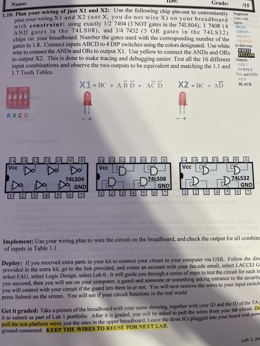
Name: Grade: /15 color code leputs BLUE GREEN SON DANCE 1.10. Plan your wiring of just XI and X2: Use the following chip pin-out to conveniently seemed with constraint: using exactly 1/2 7404 (3 NOT gates in the 74LS04), 1 7408 (4 AND gates in the 74LS08), and 3/4 7432 (3 OR gates in the 74LS32) chips on your breadboard. Number the gates used with the corresponding number of the gates in 1.8. Connect inputs ABCD to 4 DIP switches using the colors designated. Use white In Between wire to connect the ANDs and ORs to output X1. Use yellow to connect the ANDs and ORs to output X2. This is done to make tracing and debugging easier. Test all the 16 different cupit input combinations and observe the two outputs to be equivalent and matching the 1.1 and 1.7 Truth Tables. X1 = BC + ABD + ACD X2 = BC + AD WHITE YELLOW GR PURPLE Vee and GND RE BLACK ONYCH A B C D E Vcc Vcc Vcc D 74LS04 GND D74.508 74LS32 GND GND Implement: Use your wiring plan to wire the circuit on the breadboard, and check the output for all combina of inputs in Table 1.1 Deploy: If you received extra parts in your kit to connect your circuit to your computer via USB. Follow the dire provided in the extra kit, go to the link provided, and create an account with your fau.edu email, select LACCEI G select FAU, select Logic Design, select Lab 0. It will guide you through a series of steps to test the circuit for each im you succeed, then you will see on your computer, a guard and someone or something asking entrance to the security you will control with your circuit if the guard lets them in or not. You will now remove the wires to your input switch press Submit on the screen. You will see if your circuit functions in the real world Get it graded: Take a picture of the breadboard with your name showing together with your ID and the ID of the TA it to submit as part of Lab 1 portfolio. After it is graded, you will be asked to pull the wires from your lab circuit. Da pull the test platform wires just the ones in the upper breadboard. Leave the three ICs plugged into your board with pow ground connected. KEEP THE WIRES TO REUSE FOR NEXT LAB. Lab 1. pa
Step by Step Solution
There are 3 Steps involved in it

Get step-by-step solutions from verified subject matter experts