

Question: please i need help with this lap . EE 104 LABORATORY EXERCISE 9 THREE-PHASE SYSTEMS Instruments a personal computer running Multisam circuit simulation software A.
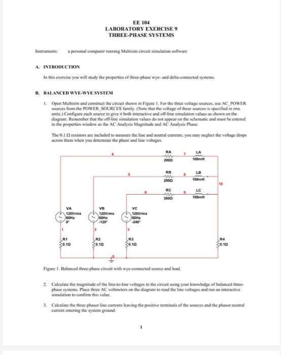
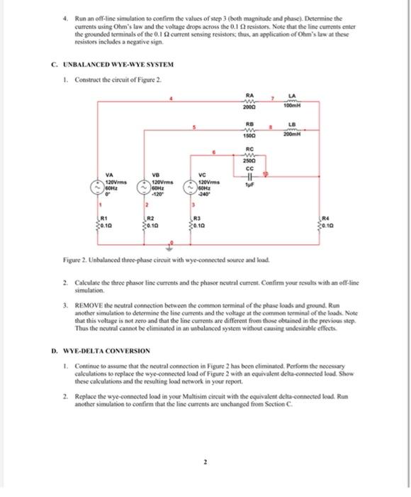
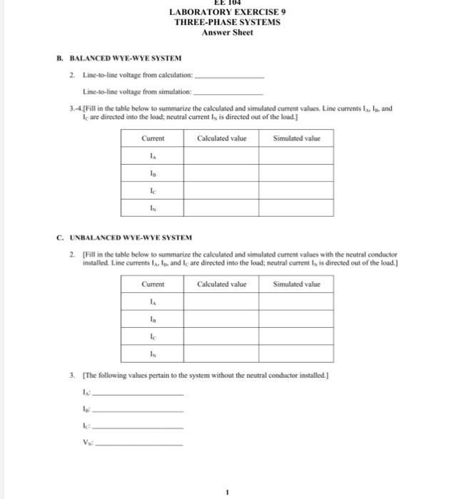
EE 104 LABORATORY EXERCISE 9 THREE-PHASE SYSTEMS Instruments a personal computer running Multisam circuit simulation software A. INTRODUCTION In this exercise you will stay the properties of three-phase wye- and delta-commented stem B. BALANCED WYE-WYE SYSTEM 1 Open Multisim and construct the circuit shown in Figure 1. For the three voltage sources, se AC POWER sources from the POWER SOURCES family. Note that the voltage of these sources is specified in s units. Configure each source to give it both interactive and off-line simulation values as shown on the diagram. Remember that the off-line simulation values do not appearce the schematic and most be entered in the properties window as the AC Analysis Magnitude and AC Analysis Phase The 0.10 resistors are included to measure the line and neutral currents you may neglect the voltage drops across them when you determine the phase and line voltages. RA 7 2000 RB w 2000 RC w 2000 100 VA 120Vrms 60Hz VB 120Vms GE VC 120Vrms GOH RI 30.10 R2 30.10 R3 30.10 R4 30.10 Figure 1. Balanced three-phase circuit with wyo connected source and load 2 Calculate the magnitude of the line-to-line voltages in the circuit using your knowledge of balanced three phase systems. Place three AC voltmeters on the diagram to read the line voltages and run an interactive Simulation to confirm this value 3. Calculate the three phasor line currents leaving the positive terminals of the sources and the phasor neutral current entering the system ground. Run an off-line simulation to confirm the values of step 3 (both magnitude and phase). Determine the currents using Ohm's law and the voltage drops across the 0.1 resistors. Note that the line currents enter the grounded terminals of the 0.1 current sensing resistors, thus, an application of Ohm's law at these resistors includes a negative sign C. UNBALANCED WYE-WYE SYSTEM 1. Construct the circuit of Figure 2. RA w 2000 100m RE w 1500 200m. RC 2500 HE VA 120Vrms BOH VO 120 Vrms -120 VC 120Vrms GOH 240 RI So.10 R2 30.10 R3 30.10 R4 30.10 Figure 2. Unbalanced three-phase circuit with Wye-connected source and load 2. Calculate the three phasor line currents and the phasor neutral current Confirm your results with an off-line simulation 3. REMOVE the neutral connection between the common terminal of the phase loads and ground. Run another simulation to determine the line currents and the voltage at the common terminal of the loads. Note that this voltage is not zero and that the line currents are different from those obtained in the previous step Thus the neutral cannot be eliminated in an unbalanced system without causing undesirable effects D. WYE-DELTA CONVERSION 1. Continue to assume that the neutral connection in Figure 2 has been eliminated Perform the necessary calculations to replace the wye-connected load of Figure 2 with an equivalent del connected lood. Show these calculations and the resulting load network in your report 2. Replace the wyc-connected load in your Multisim circuit with the equivalent delta-connected load. Run another simulation to confirm that the line currents are unchanged from Section C LABORATORY EXERCISE 9 THREE-PHASE SYSTEMS Answer Sheet B. BALANCED WYE-WYE SYSTEM 2. Line-to-line voltage from calculation: Line-to-line voltage from simulation 3.-4. [Fill in the table below to summarize the calculated and simulated current values. Line currents la, la, and le are directed into the load; neutral currently is directed out of the load] Calculated value Simulated value Current 14 I I C. UNBALANCED WYE-WYE SYSTEM 2. [Fill in the table below to summarize the calculated and simulated current values with the neutral conductor installed. Line currents ll, and I are directed into the load: neutral current la is directed out of the load) Current Calculated value Simulated value 1. Ic 1 3. [The following values pertain to the system without the neutral conducter installed.] V D. WYE-DELTA CONVERSION 1. [Neatly present the calculations needed to determine the equivalent delta-connected load. The final result must be stated in terms of the component values (resistance, inductance, capacitance) used in simulation. 2. (Attach a copy of the simulation diagram and a copy of the simulation output verifying the wye-delta equivalence) EE 104 LABORATORY EXERCISE 9 THREE-PHASE SYSTEMS Instruments a personal computer running Multisam circuit simulation software A. INTRODUCTION In this exercise you will stay the properties of three-phase wye- and delta-commented stem B. BALANCED WYE-WYE SYSTEM 1 Open Multisim and construct the circuit shown in Figure 1. For the three voltage sources, se AC POWER sources from the POWER SOURCES family. Note that the voltage of these sources is specified in s units. Configure each source to give it both interactive and off-line simulation values as shown on the diagram. Remember that the off-line simulation values do not appearce the schematic and most be entered in the properties window as the AC Analysis Magnitude and AC Analysis Phase The 0.10 resistors are included to measure the line and neutral currents you may neglect the voltage drops across them when you determine the phase and line voltages. RA 7 2000 RB w 2000 RC w 2000 100 VA 120Vrms 60Hz VB 120Vms GE VC 120Vrms GOH RI 30.10 R2 30.10 R3 30.10 R4 30.10 Figure 1. Balanced three-phase circuit with wyo connected source and load 2 Calculate the magnitude of the line-to-line voltages in the circuit using your knowledge of balanced three phase systems. Place three AC voltmeters on the diagram to read the line voltages and run an interactive Simulation to confirm this value 3. Calculate the three phasor line currents leaving the positive terminals of the sources and the phasor neutral current entering the system ground. Run an off-line simulation to confirm the values of step 3 (both magnitude and phase). Determine the currents using Ohm's law and the voltage drops across the 0.1 resistors. Note that the line currents enter the grounded terminals of the 0.1 current sensing resistors, thus, an application of Ohm's law at these resistors includes a negative sign C. UNBALANCED WYE-WYE SYSTEM 1. Construct the circuit of Figure 2. RA w 2000 100m RE w 1500 200m. RC 2500 HE VA 120Vrms BOH VO 120 Vrms -120 VC 120Vrms GOH 240 RI So.10 R2 30.10 R3 30.10 R4 30.10 Figure 2. Unbalanced three-phase circuit with Wye-connected source and load 2. Calculate the three phasor line currents and the phasor neutral current Confirm your results with an off-line simulation 3. REMOVE the neutral connection between the common terminal of the phase loads and ground. Run another simulation to determine the line currents and the voltage at the common terminal of the loads. Note that this voltage is not zero and that the line currents are different from those obtained in the previous step Thus the neutral cannot be eliminated in an unbalanced system without causing undesirable effects D. WYE-DELTA CONVERSION 1. Continue to assume that the neutral connection in Figure 2 has been eliminated Perform the necessary calculations to replace the wye-connected load of Figure 2 with an equivalent del connected lood. Show these calculations and the resulting load network in your report 2. Replace the wyc-connected load in your Multisim circuit with the equivalent delta-connected load. Run another simulation to confirm that the line currents are unchanged from Section C LABORATORY EXERCISE 9 THREE-PHASE SYSTEMS Answer Sheet B. BALANCED WYE-WYE SYSTEM 2. Line-to-line voltage from calculation: Line-to-line voltage from simulation 3.-4. [Fill in the table below to summarize the calculated and simulated current values. Line currents la, la, and le are directed into the load; neutral currently is directed out of the load] Calculated value Simulated value Current 14 I I C. UNBALANCED WYE-WYE SYSTEM 2. [Fill in the table below to summarize the calculated and simulated current values with the neutral conductor installed. Line currents ll, and I are directed into the load: neutral current la is directed out of the load) Current Calculated value Simulated value 1. Ic 1 3. [The following values pertain to the system without the neutral conducter installed.] V D. WYE-DELTA CONVERSION 1. [Neatly present the calculations needed to determine the equivalent delta-connected load. The final result must be stated in terms of the component values (resistance, inductance, capacitance) used in simulation. 2. (Attach a copy of the simulation diagram and a copy of the simulation output verifying the wye-delta equivalence)
Step by Step Solution
There are 3 Steps involved in it

Get step-by-step solutions from verified subject matter experts