

Question: please i need the solution for b and c and i'll attach the assembly code begin{tabular}{|l|l|} hline Memory Address & Contents hline 10 &

![& Load R0, [20] (instruction) \\ \hline 11 & Load R1,21 \\](https://dsd5zvtm8ll6.cloudfront.net/si.experts.images/questions/2024/09/66f2f39b7644f_10766f2f39b18e42.jpg)
![\hline 12 & Add R0, [R1] (instruction) \\ \hline 13 & load](https://dsd5zvtm8ll6.cloudfront.net/si.experts.images/questions/2024/09/66f2f39c21afc_10766f2f39ba4f27.jpg) please i need the solution for b and c and i'll attach the assembly code
please i need the solution for b and c and i'll attach the assembly code
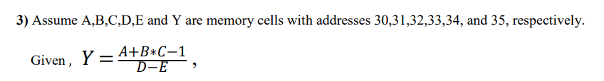
\begin{tabular}{|l|l|} \hline Memory Address & Contents \\ \hline 10 & Load R0, [20] (instruction) \\ \hline 11 & Load R1,21 \\ \hline 12 & Add R0, [R1] (instruction) \\ \hline 13 & load R1, [22] (instruction) \\ \hline 14 & Sub R1, +8 (instruction) \\ \hline 15 & Add R0,R1 (instruction) \\ \hline 16 & Store R0, [23] (instruction) \\ \hline & \\ \hline 20 & 6 (data) \\ \hline 21 & 4 (data) \\ \hline 22 & 13 (data) \\ \hline 23 & 0 (data) \\ \hline 24 & 0 (data) \\ \hline \end{tabular} 3) Assume A,B,C,D,E and Y are memory cells with addresses 30,31,32,33,34, and 35 , respectively. Given, Y=DEA+BC1, b) Convert the above assembly instructions into machine code and store them in the memory starting at address 10. c) Set PC=10 and simulate the above program. Verify that it works correctly and the result stored at memory variable Y is correct. Attach simulation waveform and the Verilog source file. Assume A, B, C, D and E have the values 1,3,5,8, and 4 , respectively
Step by Step Solution
There are 3 Steps involved in it

Get step-by-step solutions from verified subject matter experts