

Question: Please list steps. I will rate, thank you. Exercise 1: A multiplexer is shown at the figure below. The chip has eight inputs and one
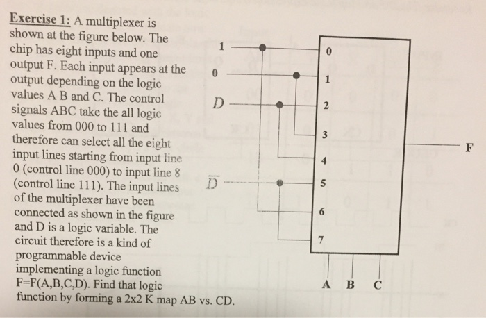
Exercise 1: A multiplexer is shown at the figure below. The chip has eight inputs and one output F. Each input appears at the output depending on the logic values A B and C. The control signals ABC take the all logic values from 000 to 111 and therefore can select all the eight input lines starting from input line 0 (control line 000) to input line 8 (control line 111). The input lines of the multiplexer have been connected as shown in the figure and D is a logic variable. The 0 5 circuit therefore is a kind of programmable device implementing a logic function A BC F-F(A,B,C,D). Find that logic function by forming a 2x2 K map AB vs. CD
Step by Step Solution
There are 3 Steps involved in it

Get step-by-step solutions from verified subject matter experts