

Question: PLEASE MAKE SURE EVERYTHING IS CORRECT AND MAKE THE CIRCUIT: Objective To derive and implement a synchronous sequential circuit Components ICs: NOT ( 7 4
PLEASE MAKE SURE EVERYTHING IS CORRECT AND MAKE THE CIRCUIT:
Objective
To derive and implement a synchronous sequential circuit
Components
ICs: NOT Input AND Input OR Input XOR D flipflop JK flipflop Resistors, LEDs, BCD to Segment Converter or Common AnodeSegment Display Common Anode
Lab equipment: breadboard, power supply, function generator, multimeter
Problem
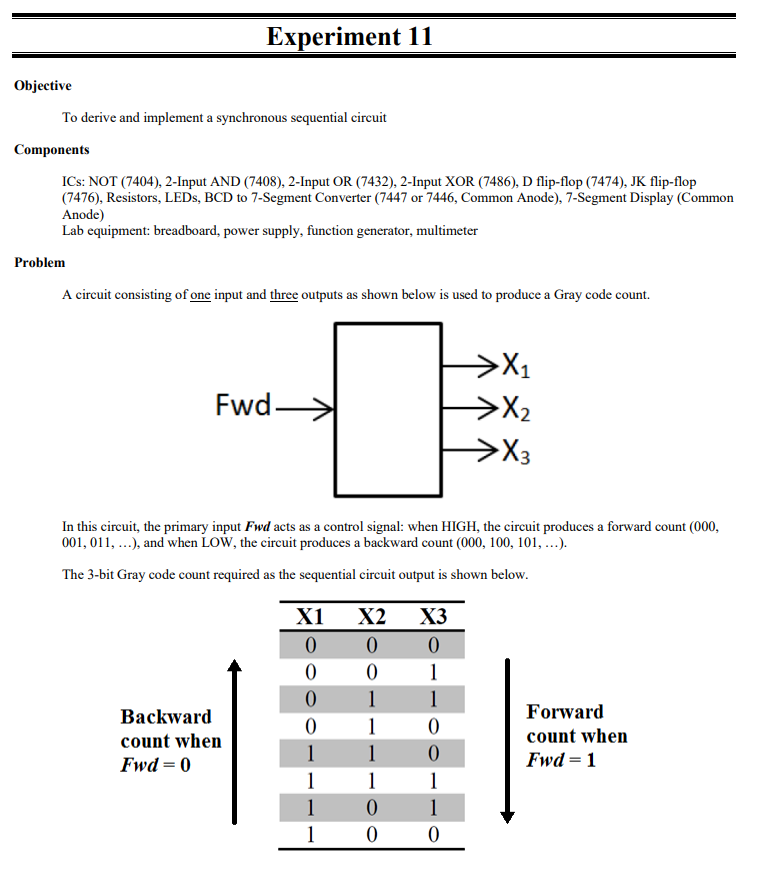
A circuit consisting of one input and three outputs as shown below is used to produce a Gray code count.
In this circuit, the primary input boldsymbolF w d acts as a control signal: when HIGH, the circuit produces a forward count ldots and when LOW, the circuit produces a backward count ldots
The bit Gray code count required as the sequential circuit output is shown below.
Backward count when boldsymbolF w dmathbf
Forward count when boldsymbolF w d
Prelab
Perform the basic steps of design of sequential circuits by:
a Fully understand the given specifications.
b Use the specifications to create a state graph.
c Use the state graph to create a state table.
d Choose a state assignment and use it to create a state assigned table.
e Choose a flipflop type and use it to create an excitation table.
f From the excitation table, derive Kmaps and equations for the input equations.
g From the state assigned table, derive Kmaps and equations for the output equations.
h Design logic to implement the input and output equations.
i Create a finished schematic.
Optional: Use Logisim to simulate.
In the lab
Important Note: Pins and of the BCD Converter are the lamp test, blanking, and ripple blanking input
pins respectively. Based on the datasheet, these pins need to be connected to a value of for proper device operation.
WARNING: Every segment in the segment component is an LED. Therefore, DO NOT FORGET TO INCLUDE
A RESISTOR FOR EVERY LED SEGMENT!! Failing to do so will destroy the component!
Implement the circuit obtained in the Prelab section.
Step by Step Solution
There are 3 Steps involved in it
1 Expert Approved Answer
Step: 1 Unlock

Question Has Been Solved by an Expert!
Get step-by-step solutions from verified subject matter experts
Step: 2 Unlock
Step: 3 Unlock