

Question: Please make sure the solution is correct and show step by step for thumbs up. D (FPGA Placement and Routing 10 points) Refer to Fig.
 Please make sure the solution is correct and show step by step for thumbs up.
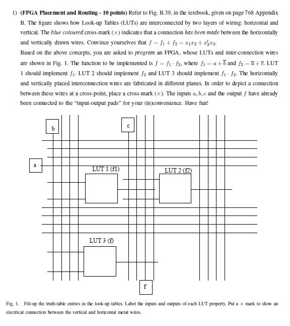
D (FPGA Placement and Routing 10 points) Refer to Fig. B.39, in the textbook, given on page 768 Appendix B. The figure shows how Look-up Tables (LUTs) are interconnected by two layers of wiring: horizontal and vertical The blue coloured cross-mark (x) indicates that a connection has been made between the horizontally and vertically drawn wires. Convince yourselves that f f1 + f-112 +13. Based on the above concepts, you are asked to program an FPGA, whose LUTs and inter-connection wires are shown in Fig. 1. The function to be implemented is f = fi .fa, where fi = a + b and f2 =-+-LUT I should implement fi. LUT 2 should implement f2 and LUT 3 should implement fi fz. The horizontally and vertically placed interconnection wires are fabricated in different planes. In order to depict a connection between these wires at a cross-point, place a cross-mark (x). The inputs a, b, e and the output f have already been connected to the "input-output pads" for your (in)convenience. Have fun! LUT 1 (fl) LUT 3 (f) Fig. 1 Fill-up the truth-table entries in the look-up tables. Label the imputs and outputs of each LUT property. Put a x mark to show an electrical connection between the vertical and horizontal metal wires D (FPGA Placement and Routing 10 points) Refer to Fig. B.39, in the textbook, given on page 768 Appendix B. The figure shows how Look-up Tables (LUTs) are interconnected by two layers of wiring: horizontal and vertical The blue coloured cross-mark (x) indicates that a connection has been made between the horizontally and vertically drawn wires. Convince yourselves that f f1 + f-112 +13. Based on the above concepts, you are asked to program an FPGA, whose LUTs and inter-connection wires are shown in Fig. 1. The function to be implemented is f = fi .fa, where fi = a + b and f2 =-+-LUT I should implement fi. LUT 2 should implement f2 and LUT 3 should implement fi fz. The horizontally and vertically placed interconnection wires are fabricated in different planes. In order to depict a connection between these wires at a cross-point, place a cross-mark (x). The inputs a, b, e and the output f have already been connected to the "input-output pads" for your (in)convenience. Have fun! LUT 1 (fl) LUT 3 (f) Fig. 1 Fill-up the truth-table entries in the look-up tables. Label the imputs and outputs of each LUT property. Put a x mark to show an electrical connection between the vertical and horizontal metal wires
Step by Step Solution
There are 3 Steps involved in it

Get step-by-step solutions from verified subject matter experts