

Question: please note, that there are four inputs s0= 00 s1= 01 s2=11 s3=10 the previous solution you are considered that there are two inputs, please
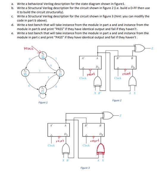
a. Write a behavioral Verilog description for the state diagram shown in figure1. b. Write a Structural Verilog description for the circuit shown in figure 2 (i.e. build a D-FF then use it to build the circuit structurally). c. Write a Structural Verilog description for the circuit shown in figure 3 (hint: you can modify the code in part b above). d. Write a test bench that will take instance from the module in part a and and instance from the module in part b and print "PASS" if they have identical output and fail if they haven"t . e. Write a test bench that will take instance from the module in part a and and instance from the module in part c and print "PASS" if they have identical output and fail if they haven't
Step by Step Solution
There are 3 Steps involved in it

Get step-by-step solutions from verified subject matter experts