

Question: please only draw the Hydraulic grade line for the fully worked question below a rough sketch is fine A3 KXAMPLE 3 A pump is required
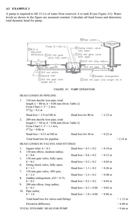
A3 KXAMPLE 3 A pump is required to lif 35L s of water from reservoir A to tank B (see Figure A1 ). Water levels as shown in the figure are assumed constant. Calculate all bead lesses and determine total dyaamic head for pump. FIGURE AT PUMP OPERATION IIEAD LOSSES IN PIPELINE 1. 150 min ductile iron pipe; total length L=80m;=0.06 am (from Table 2) From Chart 5:V=2m/s; y2/2g=0.2m Head loss =2.9m/100m Head loss for 80m=232m 2. 200mm ductile iron pipe; total leagth L=40ma;=0.06 am (from Table 2) From Chart 5: V=1.1m/s; 2/2g=0.06m Head loss =0.55m/100m Head loss for 40m=0.22m Total head loss for pipeline 2.54m HEAD LOSSES IN VALVES AND FTTTINGS 3. Square inlet: k=0.5 4. 150mm elhow, medium radius; k=0.6 5. 150 mm gate valve, fully open; k=0.2 6. Swing chock valve, fully open; k=1.3 7. 150 mm gate valve, 50% pen; k=2.4 8. Sudden enlargeneet, dD=0.75 : k=0.2 9. 200mm ellew, long radius: i=03 10. Mipe outlet; i=1.0 Head loss =0.50.2=0.10m Head loss =0.60.2=0.12m Head loss =0.20.2=0.04m Ilead loss =1.30.2=0.26m Heat loss =2.40.2=0.4k m Head loss =0.20.2=0.04m Head loss =0.30.060.02m Ilead loss =1.00.06=0.06m Total head hoss for valves and fittings Elevation difference TOTAL. DYNAMIC IIEAD FOE FUMP 1.12m -6.00 m =9.66m
Step by Step Solution
There are 3 Steps involved in it

Get step-by-step solutions from verified subject matter experts