

Question: Please provide vhdl code and testbench photos too please provide vhdl code and tesbench too Write a structural VhDL code. You Must create (or re-use)
Please provide vhdl code and testbench photos too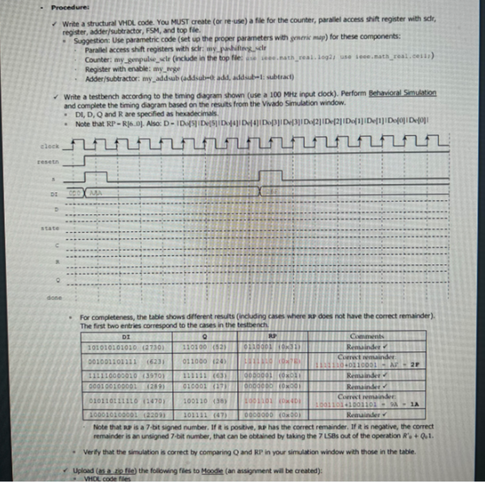
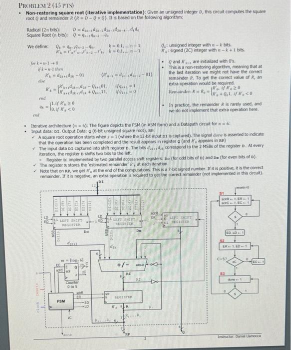
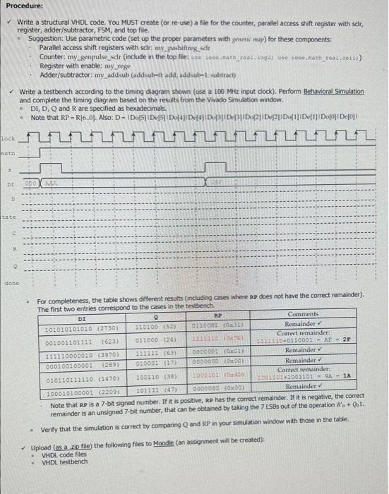
Write a structural VhDL code. You Must create (or re-use) a file for the counter, parallel access shift register with sdr, register, adder/subtractor, FSM, and top file. Suggestion: Use parametric code (set up the proper parameters with grieric map) for these components: - Parallel access shift registers with sclr: my _pahiftiny uelr - Counter: any genpulwe_olr (include in the top fie; wne ieee. path_real. aeg2y use ieee. nath_real. cetal) - Register with enable: my nege - Adder/subtractor: my addwub (addisulue0, add, audsub-1: subtract) Write a testbench according to the timing diagram shown (use a 100Mriz ingut cock). Perform Behavioral Simulation and complete the timing diagram based on the results from the Vivado Simulation window. * DI, D, Q and R are specified as hexadecimals. - For completeness, the table shows different results (including cases where so does not have the correct remainder). The first two entries corresoond to the cases in the testbench. " Fote that s. is a 7-bit signed number. If it is positive, a. has the correct remainder. If it is negative, the correct remainder is an unsigned 7 -bit number, that can be obtained by taking the 7 L sis out of the operation R. + Qot. - Verify that the simulation is correct by comparing Q and RP? in your simulation window with those in the table. Upload (as a zip file) the following files to Moode (an assignment will be created): PROBLFA 2 ( LO PIS) Non-restoring square root (iterative implementation): Given an unsigned integer D, this oircut computes the square root Q and remainder R(R=DQQ). It is based on the following aigorath: Radical(2nbits);SquareRoot(nbits):D=d2n1dn1d2n4d2nd1deQ=qn1qn2qn We define: Q4 : unsigned integer wth nk bits. Rz2 : signed (2C) integer with nk+1 bits. forkn10if151then (din1=d2n+1din20T) - Q and Rn1 are intialized with . - This is a non-estoring algorithm, meaning that at the last teration we might not have the correct renander R. To get the contect value of R, an eatra operation would be required. - In practice, the remainder R is rarely used, and we do not implenent that extra operation here. - Iterative architecture (n=6); The figure depicts the FSM (in ASM form) and a Datapoth crcut for n=6 : - Input data: or. Output Data: Q ( 6 -bit unsigned square root), RP. - A square toot operation starts when s=1 ( where the 12 -bit input or is captured). The sigal dine is asserted to indicate that the operation has been completed and the result appears in register 0 (and Rs appears in 2P ) The input data DI captured into shit register D. The bis d24.1d2k correspond to the 2 MSEs of the register D. At every iteration, the register D shifts two bts to the lef. - Register D : implemented by two parallel access stitt regsters: Do (lor odd bets of D ) and De (foc even bits of D ). 6 The register r stores the 'estimated remainder' R2 at exch teration. - Note that on Re, we get Rb at the end of the computations. This is a 7 bit signed number. If it is positie, 2 is the correct Procedure: Write a structural VHDL code. You MuST create (or re-use) a file for the counter, parallel access shift register with scir, register, adder/subtractor, FSM, and top file. * Suggestion: Use parametric code (set up the proper parameters with grieric map) for these components: - Parallel access shift registers with sdr: my pashiflirez_idt - Counter; my_genpulse_selr (include in the top fle: we iece math_raak.1og21 490 +5es, nath_reab.ceibi) - Register with enable: my_rege - Adder/subtractor: my_add cub (addvab-0: add, add vot-1 a abtrac1) Write a testbench according to the timing diagram shown (use a 100 Mhtz input dock). Perform Behavional Simulation and complete the timing diagram based on the results from the Vivado Simulaticn window. - D1, D, Q and R are specified as hexadecimals. - For completeness, the table shows different results foncluding caves where foe does not have the correct remainder). * Verify that the simulation is correct by comparing Q and RP in your simulation window with those in the table. Upload (as a xip file) the following files to Moodle (an assigsment will be created): - VHDL code files - VHDL testberch
Step by Step Solution
There are 3 Steps involved in it

Get step-by-step solutions from verified subject matter experts