

Question: please show your work 1. Consider AND Rd, Rn, Rm. For this instruction, what are the values of the control signals shown in the figure?
please show your work
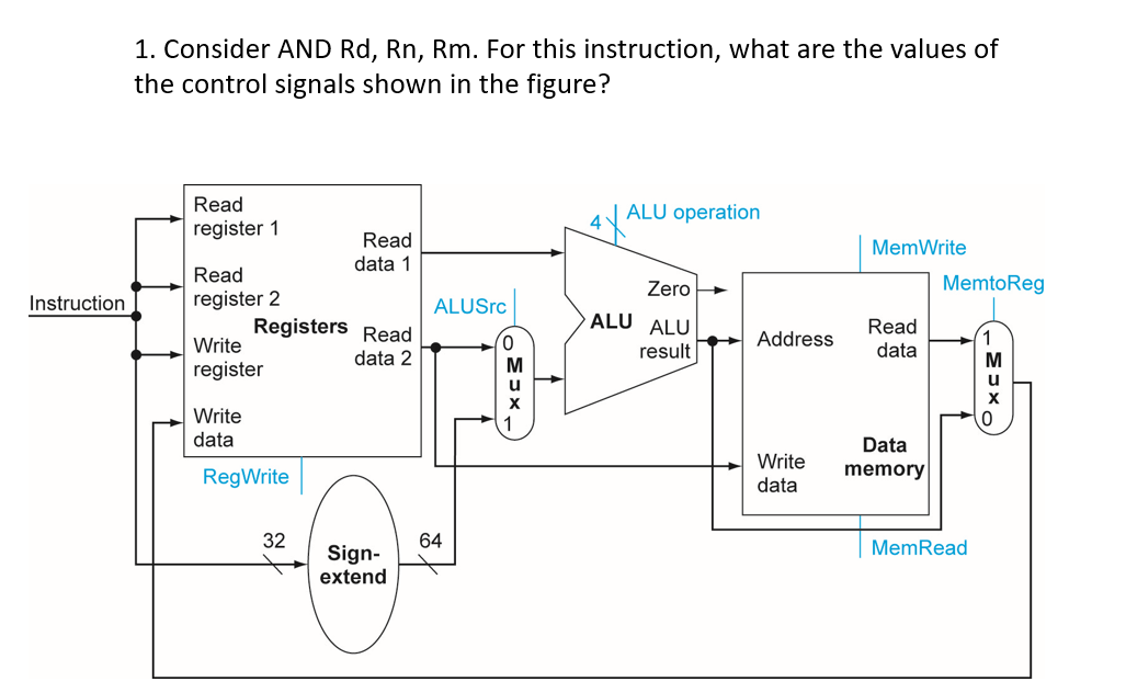
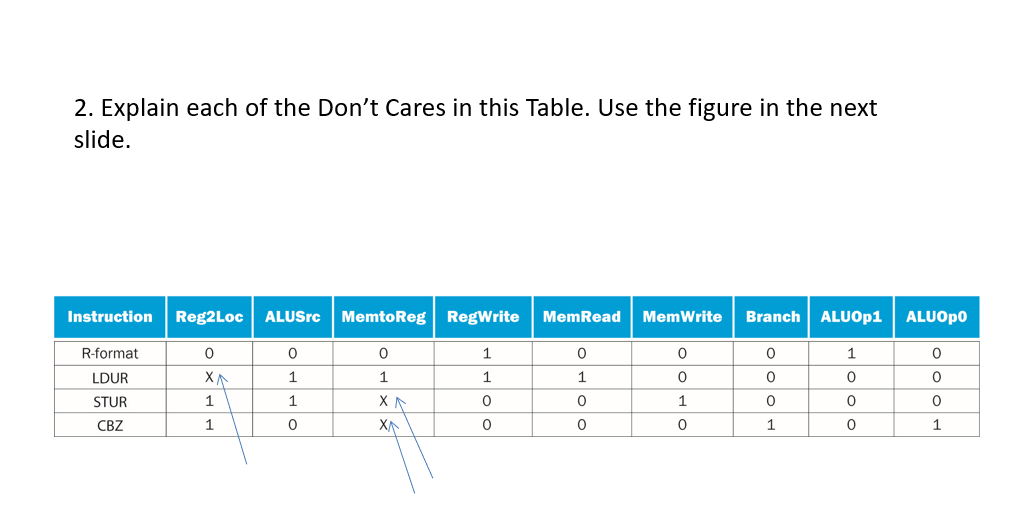
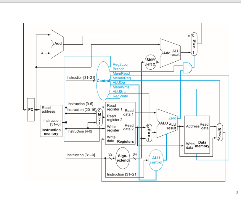
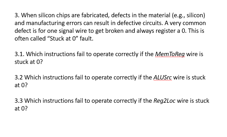
1. Consider AND Rd, Rn, Rm. For this instruction, what are the values of the control signals shown in the figure? Read register 1 4X ALU operation Read data 1 Read register 2 Mem Write MemtoReg Zero Instruction ALUSIC Registers Read ALU ALU Address Read data Write register - data 2 OES result Write data Data Write data memory RegWrite 64 MemRead Sign- extend 2. Explain each of the Don't Cares in this Table. Use the figure in the next slide. Instruction Reg2Loc ALUSrc MemtoReg RegWrite MemRead Mem Write Branch ALUOP1 ALUOPO 0 0 XA 1 0 1 R-format LDUR STUR CBZ 1 1 1 0 0 0 1 0 0 0 0 1 0 0 0 0 1 1 0 0 0 0 0 0 1 1 1 0 X Shift left 2 Reg2Loc Branch MemRead MemtoReg Instruction (31-21) Control ALUOP MemWrite ALUSrc RegWrite Read PC Instruction (9-5] Instruction (20-1610 Read address register 1 Read Read data 1 Zero Instruction (31-0] Instruction memory register 2 Write Read ALU ALU result Read Address data Instruction (4-0) register data 2 Write data Registers Write Data data memory Instruction (31-01 32 Sian. Sign- 64 ALU extend control Instruction (31-21) w 3. When silicon chips are fabricated, defects in the material (e.g., silicon) and manufacturing errors can result in defective circuits. A very common defect is for one signal wire to get broken and always register a 0. This is often called "Stuck at 0" fault. 3.1. Which instructions fail to operate correctly if the Mem ToReg wire is stuck at 0? 3.2 Which instructions fail to operate correctly if the ALUSrc wire is stuck at 0? 3.3 Which instructions fail to operate correctly if the Reg2Loc wire is stuck at O? 1. Consider AND Rd, Rn, Rm. For this instruction, what are the values of the control signals shown in the figure? Read register 1 4X ALU operation Read data 1 Read register 2 Mem Write MemtoReg Zero Instruction ALUSIC Registers Read ALU ALU Address Read data Write register - data 2 OES result Write data Data Write data memory RegWrite 64 MemRead Sign- extend 2. Explain each of the Don't Cares in this Table. Use the figure in the next slide. Instruction Reg2Loc ALUSrc MemtoReg RegWrite MemRead Mem Write Branch ALUOP1 ALUOPO 0 0 XA 1 0 1 R-format LDUR STUR CBZ 1 1 1 0 0 0 1 0 0 0 0 1 0 0 0 0 1 1 0 0 0 0 0 0 1 1 1 0 X Shift left 2 Reg2Loc Branch MemRead MemtoReg Instruction (31-21) Control ALUOP MemWrite ALUSrc RegWrite Read PC Instruction (9-5] Instruction (20-1610 Read address register 1 Read Read data 1 Zero Instruction (31-0] Instruction memory register 2 Write Read ALU ALU result Read Address data Instruction (4-0) register data 2 Write data Registers Write Data data memory Instruction (31-01 32 Sian. Sign- 64 ALU extend control Instruction (31-21) w 3. When silicon chips are fabricated, defects in the material (e.g., silicon) and manufacturing errors can result in defective circuits. A very common defect is for one signal wire to get broken and always register a 0. This is often called "Stuck at 0" fault. 3.1. Which instructions fail to operate correctly if the Mem ToReg wire is stuck at 0? 3.2 Which instructions fail to operate correctly if the ALUSrc wire is stuck at 0? 3.3 Which instructions fail to operate correctly if the Reg2Loc wire is stuck at O
Step by Step Solution
There are 3 Steps involved in it

Get step-by-step solutions from verified subject matter experts