

Question: Please solve both Problem 1 and 2 Problem 1 : The circuit shown below is a 5 t h - order Butterworth bandpass filter: Simulate
Please solve both Problem and
Problem :
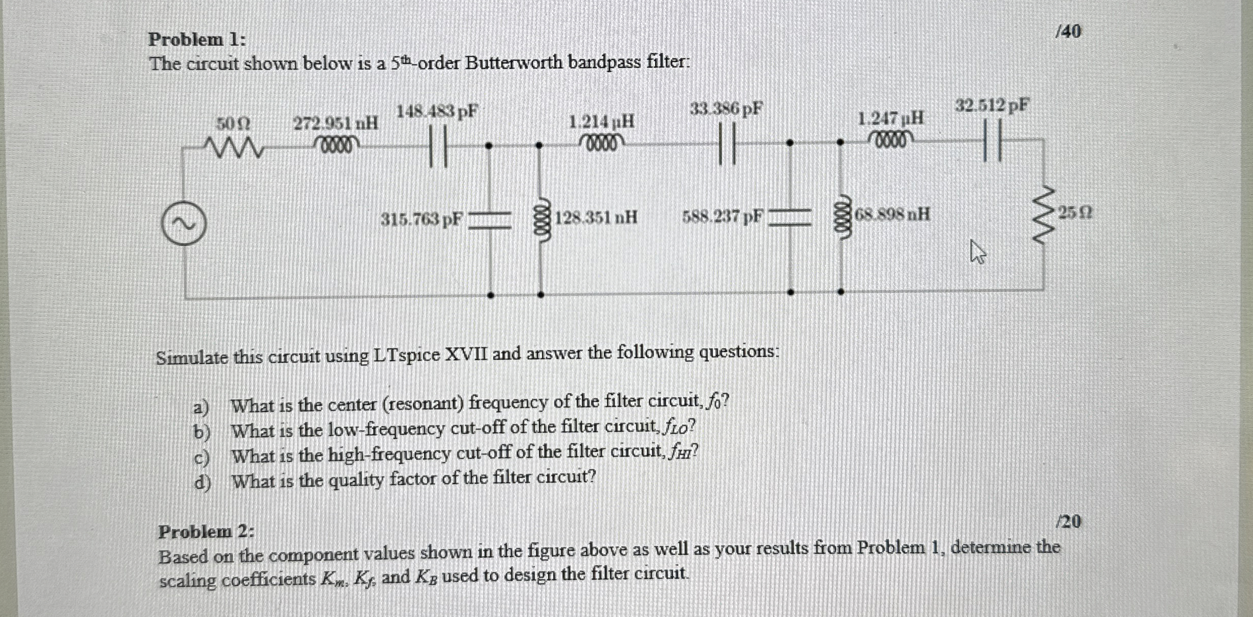
The circuit shown below is a order Butterworth bandpass filter:
Simulate this circuit using LTspice XVII and answer the following questions:
a What is the center resonant frequency of the filter circuit,
b What is the lowfrequency cutoff of the filter circuit,
c What is the highfrequency cutoff of the filter circuit,
d What is the quality factor of the filter circuit?
Problem :
Based on the component values shown in the figure above as well as your results from Problem determine the scaling coefficients and used to design the filter circuit.
Step by Step Solution
There are 3 Steps involved in it
1 Expert Approved Answer
Step: 1 Unlock

Question Has Been Solved by an Expert!
Get step-by-step solutions from verified subject matter experts
Step: 2 Unlock
Step: 3 Unlock