

Question: PLEASE SOLVE FOR PART B AND C Learning Goal: To apply the flexure formula to beams under load and find unknown stresses, moments, and forcos.
PLEASE SOLVE FOR PART B AND C Learning Goal:
To apply the flexure formula to beams under load and find unknown stresses, moments, and
forcos.
For straight members having a constant crosssection that is symmetrical with respect to an
axis with a moment appliod porpendicular to that axis, the maximum normal stress in the cross.
section can be calculated using the flexure formula:
where is the magnilude of the intemal moment with respect to the neutral axis, is the
perpendieular distance from the neutral axis to the peirt farthest from the neutral axis, and I is
the moment of inertia of the crosssection about the neutral axis. The maximum normal stress
will always occur on the top or boltom surface of the beam; in fact, one of these surfaces will
experience a maximal tensile stress while the other experiences the same magnitude of stress
in compression.
For points not on a surlace of the beam, we can use
to rowrito tho floxuro formula in the moro goneral form
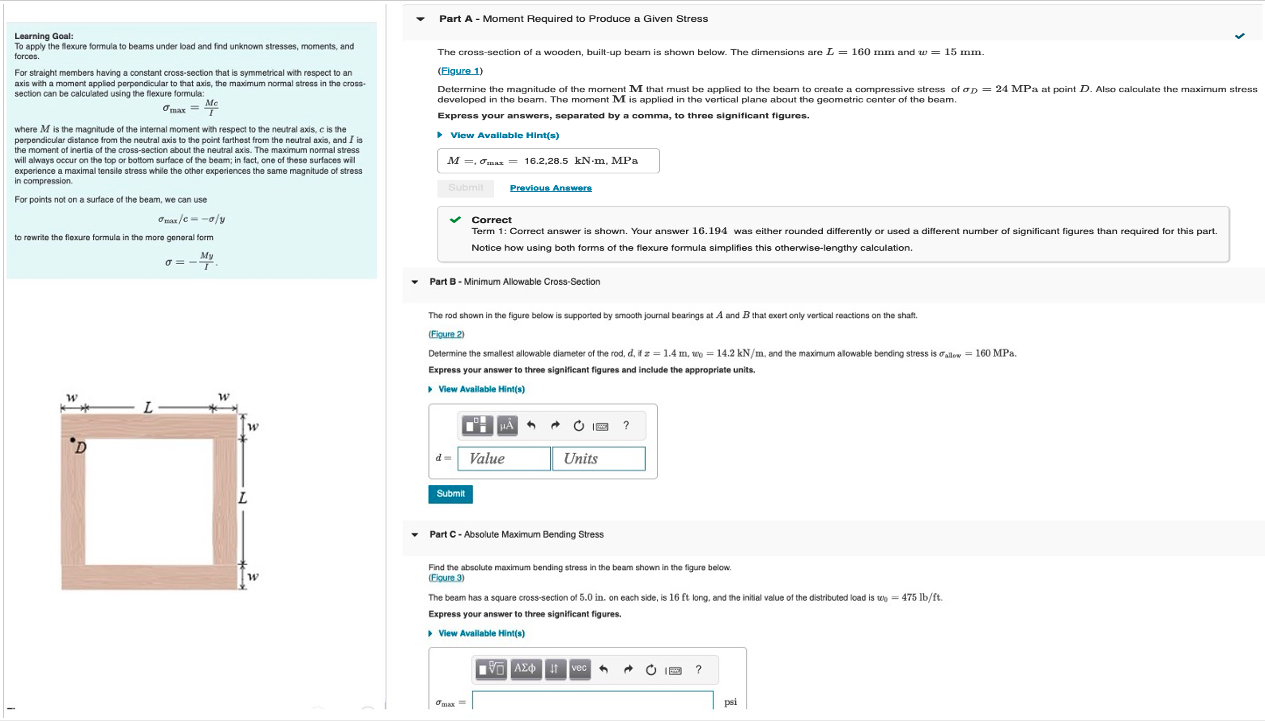
Part A Moment Required to Produce a Given Stress
The crosssection of a wooden, builtup beam is shown below. The dimensions are and
Elgure
Determine the magnitude of the moment that must be applied to the beam to create a compressive stress of MPa at point Also calculate the maximum sitress
developed in the beam. The moment is applied in the vertical plane about the geometric center of the beam.
Express your answers, separated by a comma, to three significant figures.
View Avaliable Hints
MPa
Previous Answers
Correct
Term : Correct answer is shown. Your answer was either rounded differently or used a different number of significant figures than required for this part.
Notice how using both forms of the flexure formula simplifies this otherwiselengthy calculation.
Part B Minimum Allowable CrossSection
The rod shown in the figure below is supported by smooth journal bearings at A and that exert only vertical reactions on the shaft.
Fiqure
Determine the smallest allowable diameter of the rod, if and the maximum alowable bending stress is MPa.
Express your answer to three significant figures and include the appropriate units.
View Available Hints
Part C Absolute Maximum Bending Stress
Find the absolute maximum bending stress in the beam shown in the figure below.
Figure
The beam has a square crosssection of on each side, is long, and the initial value of the distributed load is
Express your answer to three significant figures.
View Avallable Hints
Step by Step Solution
There are 3 Steps involved in it
1 Expert Approved Answer
Step: 1 Unlock

Question Has Been Solved by an Expert!
Get step-by-step solutions from verified subject matter experts
Step: 2 Unlock
Step: 3 Unlock