

Question: Please solve in Tinkercad. DC Motor with a Rotary Encoder In the first part of the experiment, we will use a DC motor with a
Please solve in Tinkercad. DC Motor with a Rotary Encoder
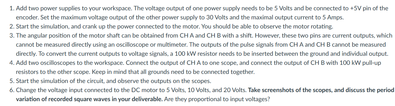
In the first part of the experiment, we will use a DC motor with a rotary encoder attached. You can find this component on Tinkercad. The pinouts of this motor are shown in Figure Add two power supplies to your workspace. The voltage output of one power supply needs to be Volts and be connected to V pin of the encoder. Set the maximum voltage output of the other power supply to Volts and the maximal output current to Amps.
Start the simulation, and crank up the power connected to the motor. You should be able to observe the motor rotating.
The angular position of the motor shaft can be obtained from mathrmCH A and CHB with a shift. However, these two pins are current outputs, which cannot be measured directly using an oscilloscope or multimeter. The outputs of the pulse signals from CH A and CH B cannot be measured directly. To convert the current outputs to voltage signals, a kW resistor needs to be inserted between the ground and individual output.
Add two oscilloscopes to the workspace. Connect the output of CH A to one scope, and connect the output of CH B with kW pullup resistors to the other scope. Keep in mind that all grounds need to be connected together.
Start the simulation of the circuit, and observe the outputs on the scopes.
Change the voltage input connected to the DC motor to Volts, Volts, and Volts. Take screenshots of the scopes, and discuss the period variation of recorded square waves in your deliverable. Are they proportional to input voltages? Fig. : Pinouts of the DC motor with rotary encoder.
Step by Step Solution
There are 3 Steps involved in it
1 Expert Approved Answer
Step: 1 Unlock

Question Has Been Solved by an Expert!
Get step-by-step solutions from verified subject matter experts
Step: 2 Unlock
Step: 3 Unlock