

Question: Please solve the questions 6.5 1and 2and 3 EXPERIMENT 6 CONTROLLER DESIGN 6.1 OBJECTIVE In this experiment we will design a controller circuit. 6.2 EQUIPMENT
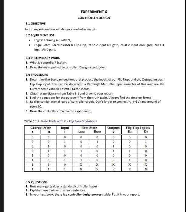
EXPERIMENT 6 CONTROLLER DESIGN 6.1 OBJECTIVE In this experiment we will design a controller circuit. 6.2 EQUIPMENT LIST Digital Training set Y-0039, Logic Gates: SN 74LS74AND Flip Flop, 7432 2 Input OR gate, 7408 2 input AND gate, 7411 3 input AND gate, 6.3 PRELIMINARY WORK 1. What is controller? Explain. 2. Draw the main parts of a controller. Design a controller. 6.4 PROCEDURE 1. Determine the Boolean functions that produce the inputs of our Flip Flops and the Output, for each Flip Flop input. This can be done with a Karnaugh Map. The input variables of this map are the Current State variables as well as the inputs. 2. Obtain state diagram from Table 6.1 and draw to your report, 3. Find the equations for the outputs Y from the truth table. Always find the simplest form) 4. Realize combinational logic of controller circuit. Don't forget to connect Vccl+5V) and ground of every IC. 5. Draw the controller circuit in the experiment. Flip Flop Inputs 1 DA Table 6.1 A State Table with D-Flip Flop Excitations Current State Input Next State B Anest Brest 0 0 1 0 0 De 0 0 0 0 0 0 1 0 0 0 -oo-oo Outputs Y 0 0 1 1 0 0 X 1 1 0 1 0 1 0 1 OOOOOXX 1 1 1 OOO 0 0 1 X 0 1 X X X X 1 6.5 QUESTIONS 1. How many parts does a standard controller have? 2. Explain these parts with a few sentences. 3. In your text book, there is a controller design process table. Put it in your report
Step by Step Solution
There are 3 Steps involved in it

Get step-by-step solutions from verified subject matter experts