

Question: please take the random data where needed and please complete the table.... fluid mechanics.... much appreciated :) Experimental Results and Calculations Time (s) Volume (Litre)
please take the random data where needed and please complete the table.... fluid mechanics.... much appreciated :)
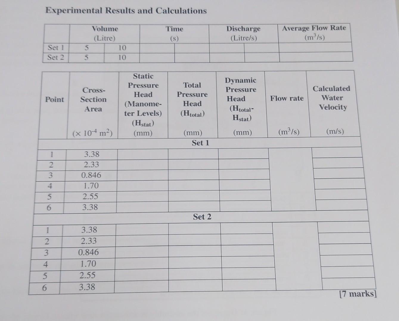
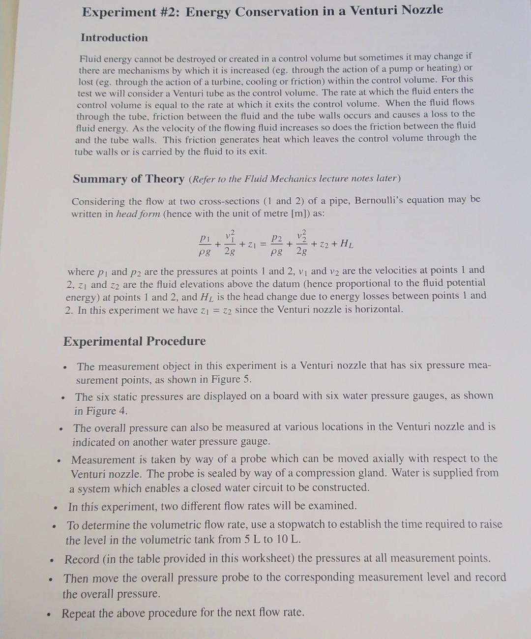
Experimental Results and Calculations Time (s) Volume (Litre) 5 10 5 Discharge (Litre/s) Average Flow Rate (m/s) Set 1 Set 2 10 Point Cross- Section Area Static Pressure Head (Manome- ter Levels) (Hstat) (mm) Total Pressure Head (Htotal) Dynamic Pressure Head (Htotal- Hstat) Flow rate Calculated Water Velocity (x 104 m2) (mm) (m/s) (m/s) (mm) Set 1 1 2 3 4 3.38 2.33 0.846 1.70 2.55 3.38 5 6 Set 2 1 2 3 3.38 2.33 0.846 1.70 2.55 3.38 4 5 6. [7 marks] Experiment #2: Energy Conservation in a Venturi Nozzle Introduction Fluid energy cannot be destroyed or created in a control volume but sometimes it may change if there are mechanisms by which it is increased (eg. through the action of a pump or heating) or lost (eg. through the action of a turbine, cooling or friction) within the control volume. For this test we will consider a Venturi tube as the control volume. The rate at which the fluid enters the control volume is equal to the rate at which it exits the control volume. When the fluid flows through the tube, friction between the fluid and the tube walls occurs and causes a loss to the fluid energy. As the velocity of the flowing fluid increases so does the friction between the fluid and the tube walls. This friction generates heat which leaves the control volume through the tube walls or is carried by the fluid to its exit. Summary of Theory (Refer to the Fluid Mechanics lecture notes later) Considering the flow at two cross-sections (1 and 2) of a pipe, Bernoulli's equation may be written in head form (hence with the unit of metre [m]) as: Piv V2 P2 + + 21 = + + Z2 + HL pg 2g pg 2g where pi and p2 are the pressures at points 1 and 2, vi and v2 are the velocities at points 1 and 2, zand z2 are the fluid elevations above the datum (hence proportional to the fluid potential energy) at points 1 and 2, and HL is the head change due to energy losses between points 1 and 2. In this experiment we have z = z2 since the Venturi nozzle is horizontal. Experimental Procedure . . The measurement object in this experiment is a Venturi nozzle that has six pressure mea- surement points, as shown in Figure 5. The six static pressures are displayed on a board with six water pressure gauges, as shown in Figure 4. The overall pressure can also be measured at various locations in the Venturi nozzle and is indicated on another water pressure gauge. Measurement is taken by way of a probe which can be moved axially with respect to the Venturi nozzle. The probe is sealed by way of a compression gland. Water is supplied from a system which enables a closed water circuit to be constructed. In this experiment, two different flow rates will be examined. To determine the volumetric flow rate, use a stopwatch to establish the time required to raise the level in the volumetric tank from 5 L to 10 L. Record (in the table provided in this worksheet) the pressures at all measurement points. Then move the overall pressure probe to the corresponding measurement level and record the overall pressure. Repeat the above procedure for the next flow rate
Step by Step Solution
There are 3 Steps involved in it

Get step-by-step solutions from verified subject matter experts