

Question: Please use MULTISIM software. PLease do not attempt if you do not have MULTISIM. build each circuit with all the connections visible and please explain
Please use MULTISIM software. PLease do not attempt if you do not have MULTISIM. build each circuit with all the connections visible and please explain step by step. I ALWAYS UPLIKE. THANK YOU!
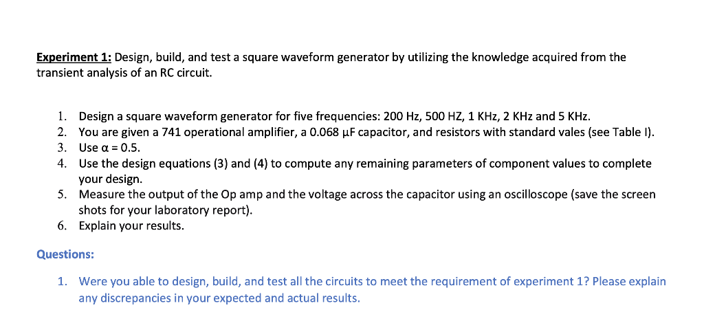
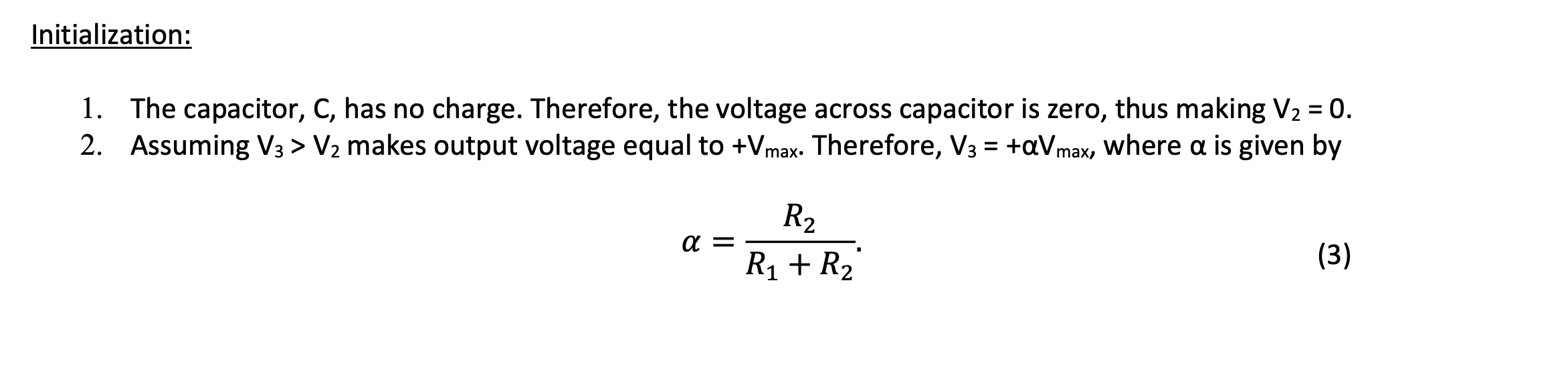
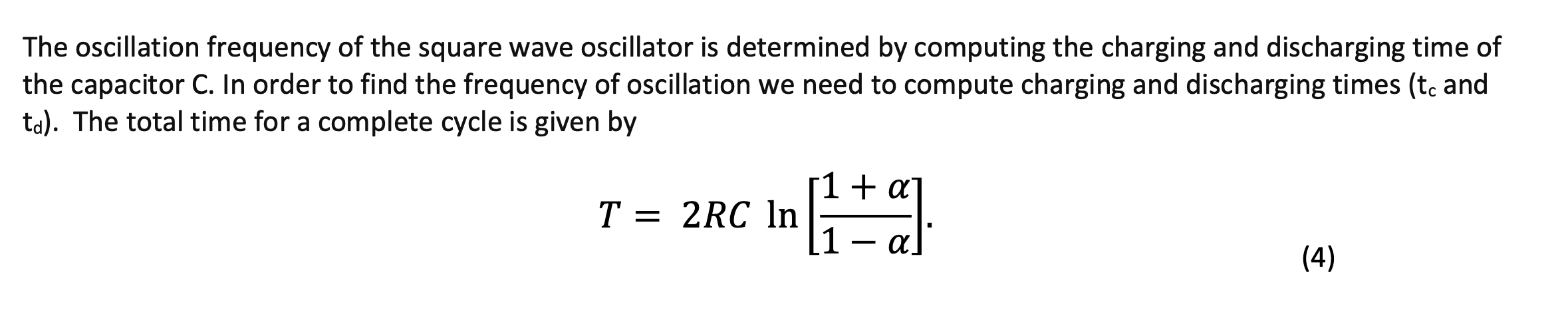
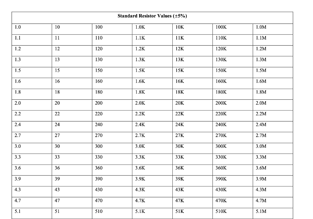
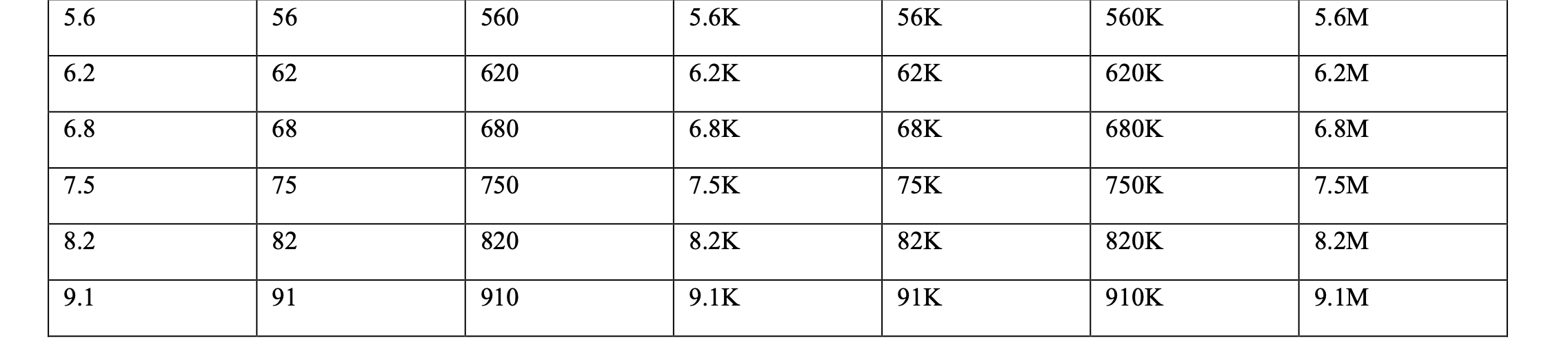
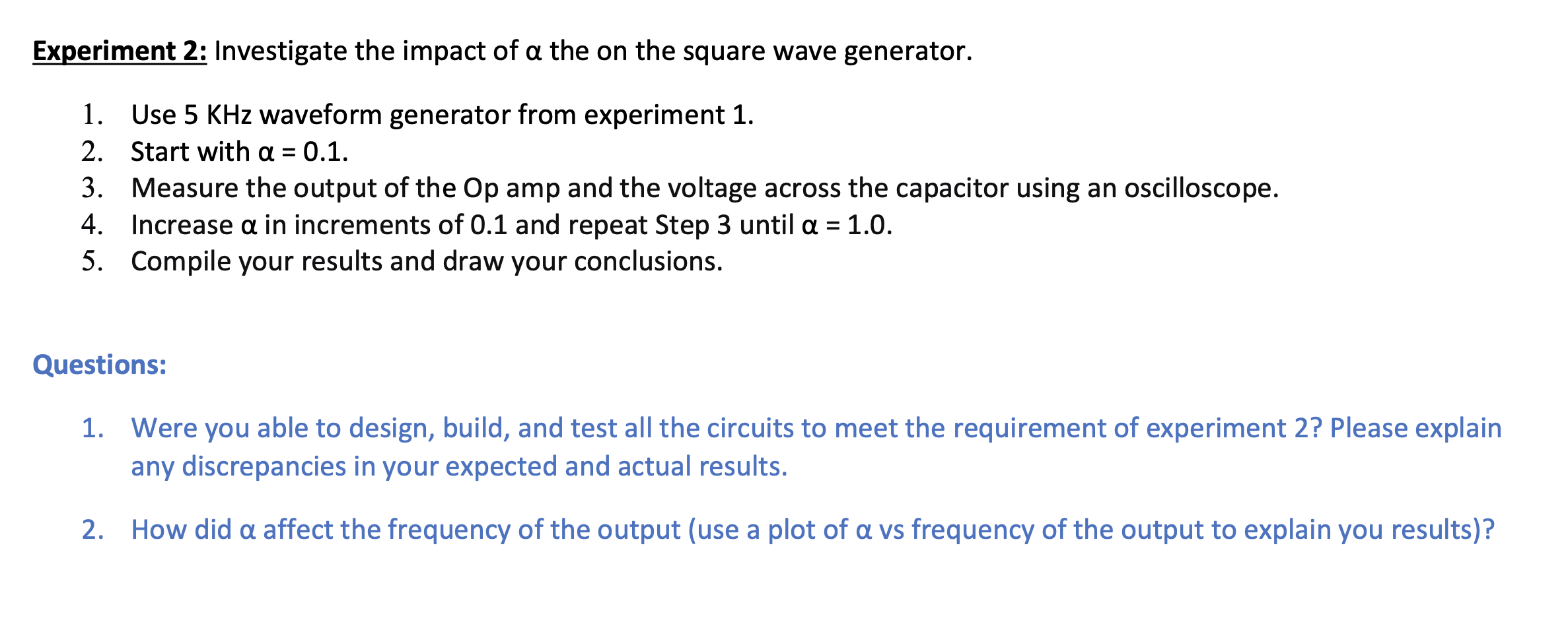
Experiment 1: Design, build, and test a square waveform generator by utilizing the knowledge acquired from the transient analysis of an RC circuit. 1. Design a square waveform generator for five frequencies: 200 Hz, 500 HZ, 1 KHz, 2 KHz and 5 KHz. 2. You are given a 741 operational amplifier, a 0.068 uF capacitor, and resistors with standard vales (see Table 1). 3. Use a = 0.5. 4. Use the design equations (3) and (4) to compute any remaining parameters of component values to complete your design. 5. Measure the output of the Op amp and the voltage across the capacitor using an oscilloscope (save the screen shots for your laboratory report). 6. Explain your results. Questions: 1. Were you able to design, build, and test all the circuits to meet the requirement of experiment 1? Please explain any discrepancies in your expected and actual results. Initialization: 1. The capacitor, C, has no charge. Therefore, the voltage across capacitor is zero, thus making V2 = 0. 2. Assuming V3 > V2 makes output voltage equal to +Vmax. Therefore, V3 = +aVmax, where a is given by R2 A = R1 + R2 (3) The oscillation frequency of the square wave oscillator is determined by computing the charging and discharging time of the capacitor C. In order to find the frequency of oscillation we need to compute charging and discharging times (tc and td). The total time for a complete cycle is given by 1 + a T = 2RC In 1- a n1=al (4) Standard Resistor Values (+5%) 1.0 10 100 1.OK 10K 100K 1.OM 1.1 11 110 1.1K 11K 110K 1.1M 1.2 12 120 1.2K 12K 120K 1.2M 1.3 13 130 1.3K 13K 130K 1.3M 1.5 15 150 1.5K 15K 150K 1.5M 1.6 16 160 1.6K 16K 160K 1.6M 1.8 18 180 1.8K 18K 180K 1.8M 2.0 20 200 2.OK 20K 200K 2.OM 2.2 22 220 2.2K 22K 220K 2.2M 2.4 24 240 2.4K 24K 240K 2.4M 2.7 27 270 2.7K 27K 270K 2.7M 3.0 30 300 3.OK 30K 300K 3.OM 3.3 33 330 3.3K 33K 330K 3.3M 3.6 36 360 3.6K 36K 360K 3.6M 3.9 39 390 3.9K 39K 390K 3.9M 4.3 43 430 4.3K 43K 430K 4.3M 4.7 47 470 4.7K 47K 470K 4.7M 5.1 51 510 5.1K 51K 510K 5.1M 5.6 56 560 5.6K 56K 560K 5.6M 6.2 62 620 6.2K 62K 620K 6.2M 6.8 68 680 6.8K 68K 680K 6.8M 7.5 75 750 7.5K 75K 750K 7.5M 8.2 82 820 8.2K 82K 820K 8.2M 9.1 91 910 9.1K 91K 910K 9.1M Experiment 2: Investigate the impact of a the on the square wave generator. 1. Use 5 KHz waveform generator from experiment 1. 2. Start with a = 0.1. 3. Measure the output of the Op amp and the voltage across the capacitor using an oscilloscope. 4. Increase a in increments of 0.1 and repeat Step 3 until a = 1.0. 5. Compile your results and draw your conclusions. Questions: 1. Were you able to design, build, and test all the circuits to meet the requirement of experiment 2? Please explain any discrepancies in your expected and actual results. 2. How did a affect the frequency of the output (use a plot of a vs frequency of the output to explain you results)
Step by Step Solution
There are 3 Steps involved in it

Get step-by-step solutions from verified subject matter experts