

Question: Please use MULTISIM software. Please do not attempt if you do not have MULTISIM. build each circuit with all the connections visible and please explain
Please use MULTISIM software. Please do not attempt if you do not have MULTISIM. build each circuit with all the connections visible and please explain step by step. I ALWAYS UPLIKE. THANK YOU!
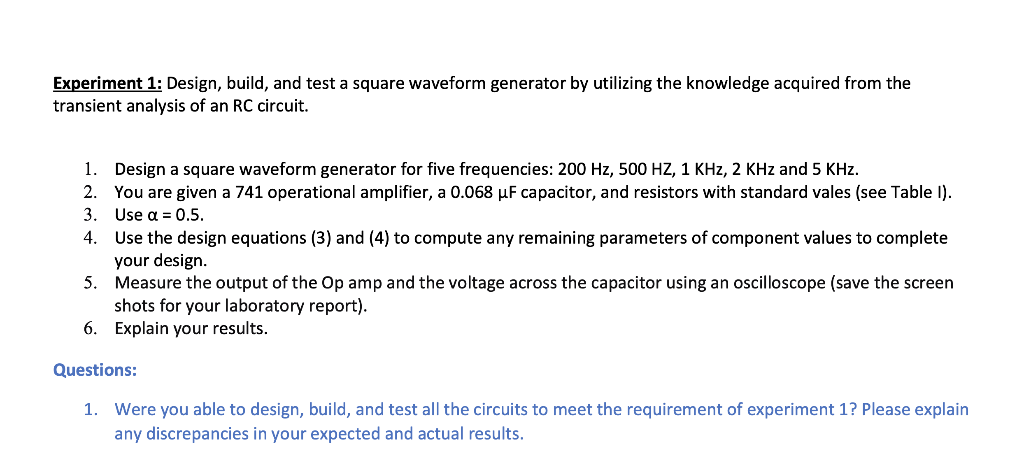
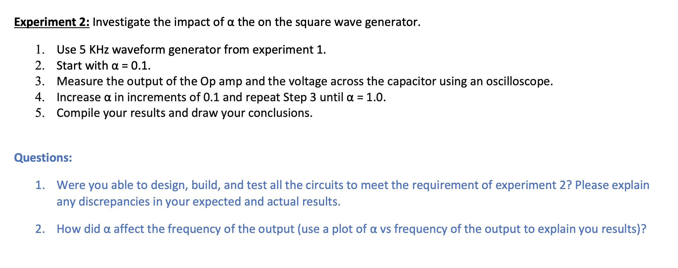
Experiment 1: Design, build, and test a square waveform generator by utilizing the knowledge acquired from the transient analysis of an RC circuit. 1. Design a square waveform generator for five frequencies: 200 Hz, 500 HZ, 1 KHz, 2 KHz and 5 KHz. 2. You are given a 741 operational amplifier, a 0.068 uF capacitor, and resistors with standard vales (see Table 1). 3. Use a = 0.5. 4. Use the design equations (3) and (4) to compute any remaining parameters of component values to complete your design. 5. Measure the output of the Op amp and the voltage across the capacitor using an oscilloscope (save the screen shots for your laboratory report). 6. Explain your results. Questions: 1. Were you able to design, build, and test all the circuits to meet the requirement of experiment 1? Please explain any discrepancies in your expected and actual results. Experiment 2: Investigate the impact of a the on the square wave generator. 1. Use 5 KHz waveform generator from experiment 1. 2. Start with a = 0.1. 3. Measure the output of the Op amp and the voltage across the capacitor using an oscilloscope. 4. Increase a in increments of 0.1 and repeat Step 3 until a = 1.0. 5. Compile your results and draw your conclusions. Questions: 1. Were you able to design, build, and test all the circuits to meet the requirement of experiment 2? Please explain any discrepancies in your expected and actual results. 2. How did a affect the frequency of the output (use a plot of a vs frequency of the output to explain you results)? Experiment 1: Design, build, and test a square waveform generator by utilizing the knowledge acquired from the transient analysis of an RC circuit. 1. Design a square waveform generator for five frequencies: 200 Hz, 500 HZ, 1 KHz, 2 KHz and 5 KHz. 2. You are given a 741 operational amplifier, a 0.068 uF capacitor, and resistors with standard vales (see Table 1). 3. Use a = 0.5. 4. Use the design equations (3) and (4) to compute any remaining parameters of component values to complete your design. 5. Measure the output of the Op amp and the voltage across the capacitor using an oscilloscope (save the screen shots for your laboratory report). 6. Explain your results. Questions: 1. Were you able to design, build, and test all the circuits to meet the requirement of experiment 1? Please explain any discrepancies in your expected and actual results. Experiment 2: Investigate the impact of a the on the square wave generator. 1. Use 5 KHz waveform generator from experiment 1. 2. Start with a = 0.1. 3. Measure the output of the Op amp and the voltage across the capacitor using an oscilloscope. 4. Increase a in increments of 0.1 and repeat Step 3 until a = 1.0. 5. Compile your results and draw your conclusions. Questions: 1. Were you able to design, build, and test all the circuits to meet the requirement of experiment 2? Please explain any discrepancies in your expected and actual results. 2. How did a affect the frequency of the output (use a plot of a vs frequency of the output to explain you results)
Step by Step Solution
There are 3 Steps involved in it

Get step-by-step solutions from verified subject matter experts