

Question: Please use my data, and show clear working, thanks TWO - POINT BEAM BENDING TEST An LVL beam will be tested in order to assess
Please use my data, and show clear working, thanks TWOPOINT BEAM BENDING TEST
An LVL beam will be tested in order to assess the validity of several key assumptions we use in
the analysis of beams. The purpose of this part of the lab activity is to provide some additional
context that may help gain a better understanding of beam bending and the key beam assump
tions we rely on in our analysis of beams and bending.
Test Setup
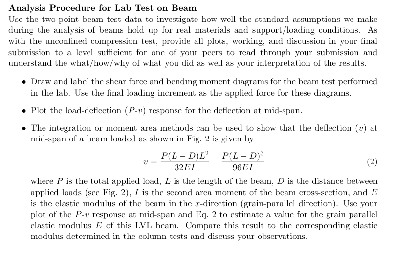
A simplysupported beam will be tested under twopoint loading as shown in Fig. This type
of loading allows for us to examine the beam response to pure bending and to pure shear. The
grain of the LVL beam is aligned with the long axis of the beam what we typically call the
axis and the beam crosssection has the orientation and approximate dimensions shown.
Figure : Layout and dimensions of twopoint beam bending test.:Test Setup
A simplysupported beam will be tested under twopoint loading as shown in Fig. This type
of loading allows for us to examine the beam response to pure bending and to pure shear. The
grain of the LVL beam is aligned with the long axis of the beam what we typically call the
axis and the beam crosssection has the orientation and approximate dimensions shown.
Figure : Layout and dimensions of twopoint beam bending test.
Experimental Procedure
In the twopoint test, the total load applied to the beam is increased incrementally with half of
the load applied at the points shown in Fig. until a specified maximum load is reached. The
deformation of the beam is measured in three different ways during this test as detailed in the
following steps:
Record the total load applied to the beam in each load increment.
Measure the deflection of the beam at midspan in each load increment using the deflec
tion gauge. Deflection is the distance that the beam moves downwards when bending.
At midspan, an array of eight demec gauges is distributed over the height of the beam in
order to measure average normal strains in the direction of the long axis of the beam at
different points along the height of the crosssection. Obtain readings from this midspan
array under zero load and for each load increment and record the positions of these gauges
relative to the top or bottom of the beam crosssection.
At approximately to the left of the right support, three demec gauges are applied
in a rosette located and aligned relative to the centerline axis of the beam as shown
in Fig. Obtain readings from this rosette under zero load and for each load increment.
Ensure that the appropriate calibration factors are recorded for all demec gauges.
Step by Step Solution
There are 3 Steps involved in it
1 Expert Approved Answer
Step: 1 Unlock

Question Has Been Solved by an Expert!
Get step-by-step solutions from verified subject matter experts
Step: 2 Unlock
Step: 3 Unlock