

Question: Please use the datapath below to answer the questions and please answer all parts correctly. Single Cycle Data Path diagram Multi Cycle Datapath Diagram Suppose
Please use the datapath below to answer the questions and please answer all parts correctly.
Single Cycle Data Path diagram
Multi Cycle Datapath Diagram
Suppose you wish to implement the following instruction in the MIPS datapath:
DCB rs, Label
DCB stands for Decrement and Branch. As with other branch instructions, Label is the branch target address, specified in the low order 16 bits of the instruction word. Register rs is in bits [25 . . 21] of the instruction word. This instruction works as follows.
Decrement the contents of register rs by 1.
If the result is zero, branch to the target address.
Update the contents of register rs with R[rs] 1.
Assume that DCB is taken, so PC should be updated to the branch target address.
(a) Describe the changes you would make to implement this instruction in the MIPs single cycle datapath given in the handout.
(b) Specify the values of the following control variables to implement this instruction with the changes you made to the MIPS single cycle datapath given in the handout.
RegDst
ALUSrc
MemToReg
RegWrite
PCSrc
MemWrite
MemRead
ALUOp just write the name of the operation here (Add, Sub, etc.):
(c) Describe the changes you would make to implement this instruction in the MIPS multicycle datapath given in the handout.
(d) Specify the complete finite state machine for the control necessary to implement DCB with the changes you made to the MIPS multicycle datapath given in the handout.
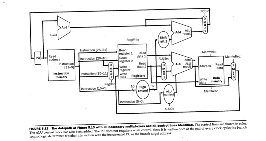
PCSrc Add ALU Add result Shift left 2 nstruction 125-211 Read MemWrite register 1. Read Read PC address data 1 MemtoReg Instruction (20-161 ALUSrc register 2 Read Instruction ALU ALU Read result Address data Write data 2 131-0) M Instruction Instruction [15-11) x write 1 rl data Registers memory Data Write data memory RegDst 16 Sign Instruction (15-ol MemRead ALU control Instruction 15-01 ALUOp FIGURE 5.17 The datapath of Figure 5.13 with all necessary multiplexors and all control lines identified. The control lines are shown in color. The ALU control block has also been added. The PC does not require a write control, since written once at the end of every clock cycle; the branch control logic determines whether written with the incremented PCor the branch target address
Step by Step Solution
There are 3 Steps involved in it

Get step-by-step solutions from verified subject matter experts