

Question: Please write using ARM Assembly for STM 3 2 F 4 1 1 VETx and an STM 3 2 Microcontroller . The modes interact with
Please write using ARM Assembly for STMFVETx and an STMMicrocontroller The modes interact with the LEDs on the board, and should be subroutines. It should all be one block of code.
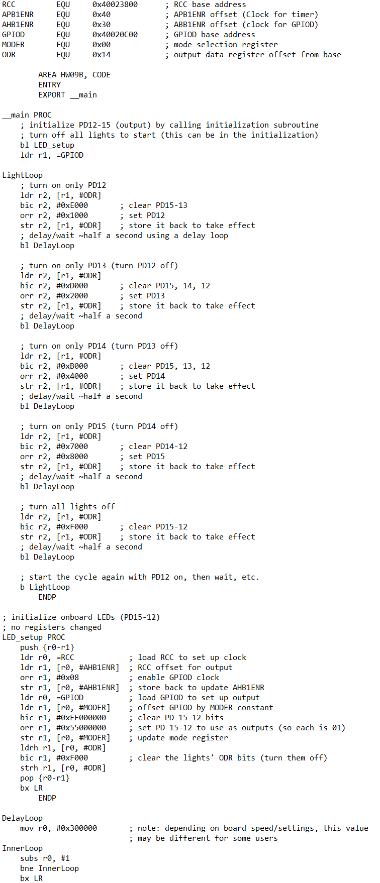
Please note the attached screenshot is an example of what our code has looked like in the past!
While the function of the attached code will not help while answering this question, im hoping it should help you understand the snytax and formatting for this code.
The final project will entail writing a program with three modes:
Mode The lights will start all off, then turn on and stay on one at a time: orange, then
red, then blue, and lastly green. They will then turn off and stay off one at a time in that
same order. Once all are off, the cycle will repeat. Put a second pause between each
change. For example, if all lights are off, the orange LED will come on and stay on then
seconds later the red LED will also come on seconds after that, the blue LED will
come on etc.
Mode B The blue light will toggleblink once per second, the red light will toggle every
seconds, the orange light will toggle every half second, and the green light will toggle every
seconds.
Mode The program will read in byte values from a nullterminated, readonly array called
ModeCVals and display them on the lights. If the value is between and the bits will
correspond such that PD represents bit PD for bit PD for bit and PD for
bit For example, if the value to be displayed is that's so PD would be
off, PD and PD would be on and PD would be off. If the value in the array is larger
than decimal fifteen do not turn on any of the lights for its representation. Each
value's LED representation should display for one second before changing directly to the
next value. The nulltermination character counts as a value its zero After displaying
the final value, loop around to the beginning of the ModCVals array and start
displaying the values from the beginning again.
The user will switch between these modes by pressing the PAO input button. The change in
mode can occur at any point during the mode as opposed to finishing the cycle of blinks
before starting the next. When the button is pressed while the program is on Mode it
should "loop around" and begin Mode A again.
Hints: Use an interrupt for the input. Debounce your input. If a timer triggers every
seconds, then something that occurs every third timer trigger will occur once every
seconds. Moving bits through to bits through is a matter of shifting. Make DATA
area values to be used as counters or to track what mode you're inThe final project will entail writing a program with three modes:
Mode A The lights will start all off, then turn on and stay on one at a time: orange, then
red, then blue, and lastly green. They will then turn off and stay off one at a time in that
same order. Once all are off, the cycle will repeat. Put a second pause between each
change. For example, if all lights are off, the orange LED will come on and stay on then
seconds later the red LED will also come on seconds after that, the blue LED will
come on etc.
Mode B The blue light will toggleblink once per second, the red light will toggle every
seconds, the orange light will toggle every half second, and the green light will toggle every
seconds.
Mode C The program will read in byte values from a nullterminated, readonly array called
ModeCVals and display them on the lights. If the value is between and the bits will
correspond such that PD represents bit PD for bit PD for bit and PD for
bit For example, if the value to be displayed is thats so PD would be
off, PD and PD would be on and PD would be off. If the value in the array is larger
than decimal fifteen xF do not turn on any of the lights for its representation. Each
values LED representation should display for one second before changing directly to the
next value. The nulltermination character counts as a value its zero After displaying
the final x value, loop around to the beginning of the ModCVals array and start
displaying the values from the beginning again.
The user will switch between these modes by pressing the PA input button. The change in
mode can occur at any point during the mode as opposed to finishing the cycle of blinks
before starting the next. When the button is pressed while the program is on Mode C it
should loop around and begin Mode A again.
Hints: Use an interrupt for the input. Debounce your input. If a timer triggers every
seconds, then something that occurs every third timer trigger will occur once every
seconds. Moving bits through to bits through is a matter of shifting. Make DATA
area values to be used as counters or to track what mode youre in
Step by Step Solution
There are 3 Steps involved in it
1 Expert Approved Answer
Step: 1 Unlock

Question Has Been Solved by an Expert!
Get step-by-step solutions from verified subject matter experts
Step: 2 Unlock
Step: 3 Unlock