

Question: Answer Problem 1. Designing A Simple 4-bit ALU A DATA B Ao A Az A3 Bo B B2 B3 MODE M 4-BIT ALU S So
Answer Problem 1.
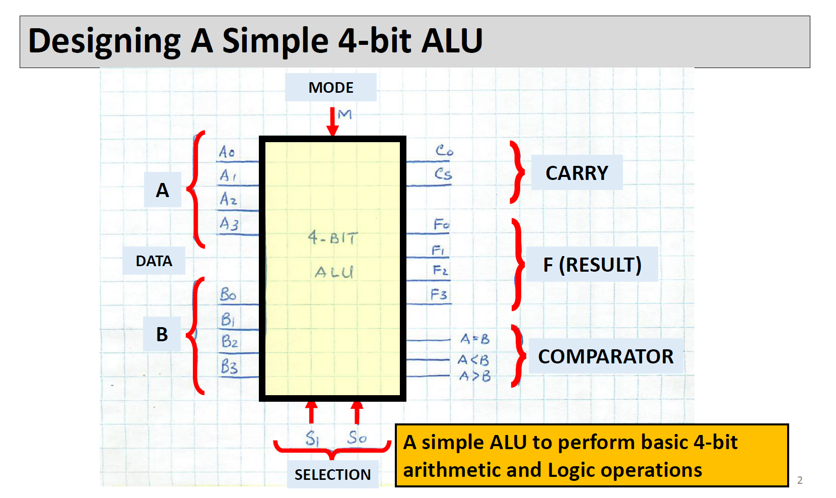
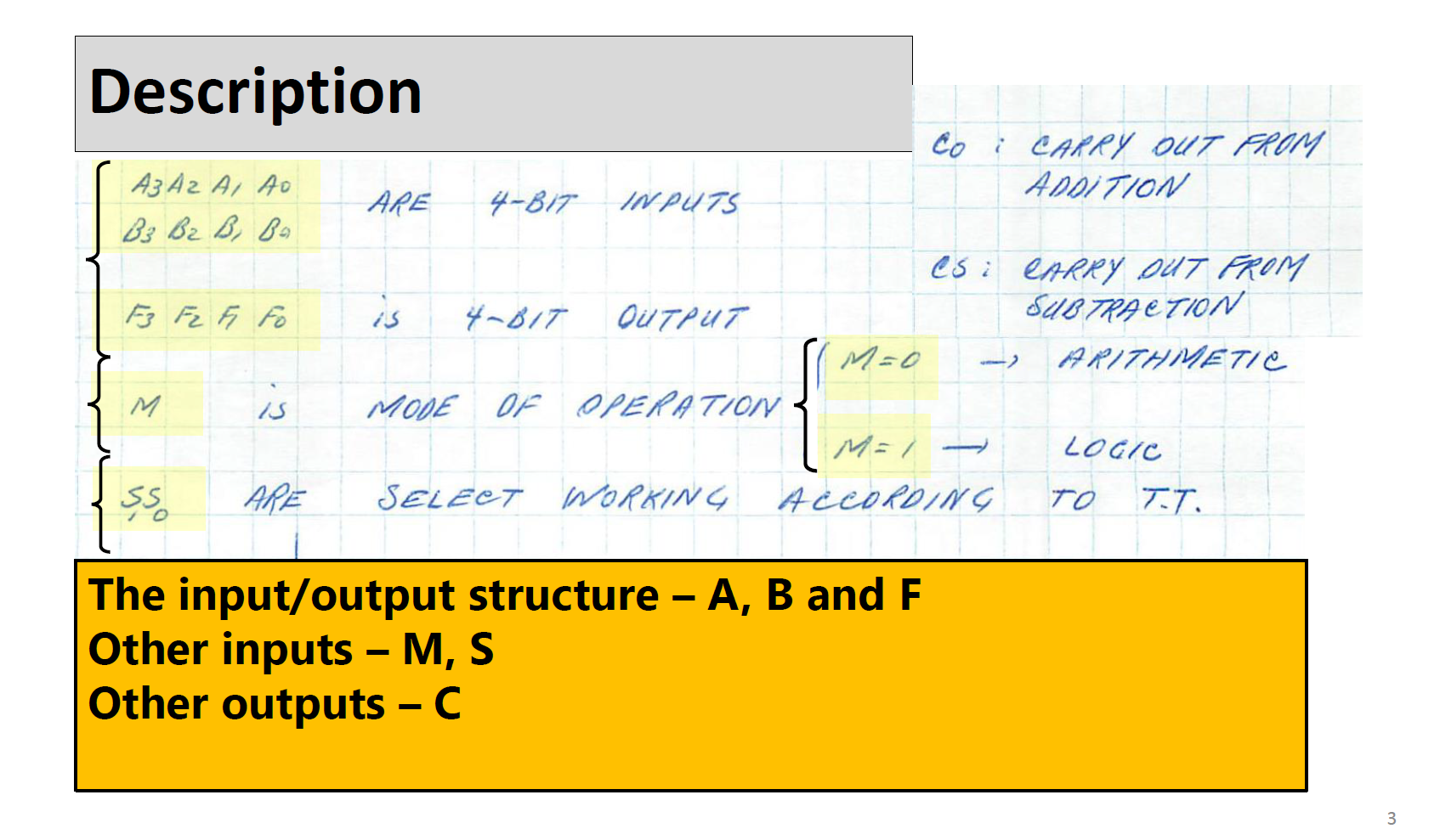
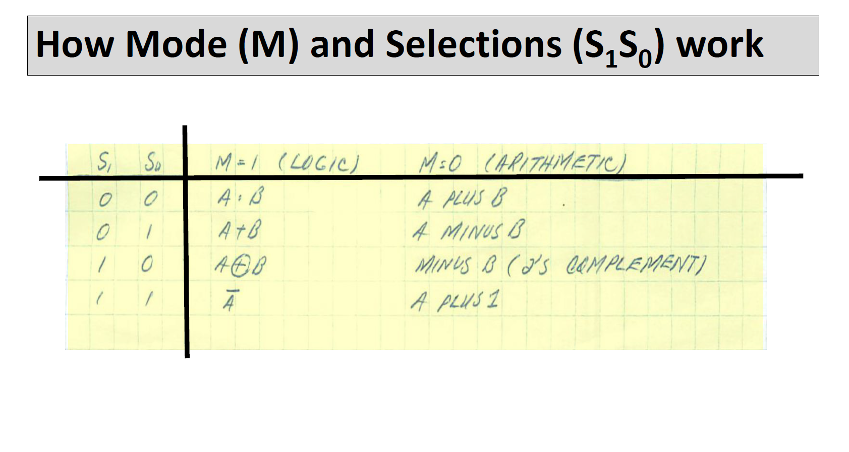
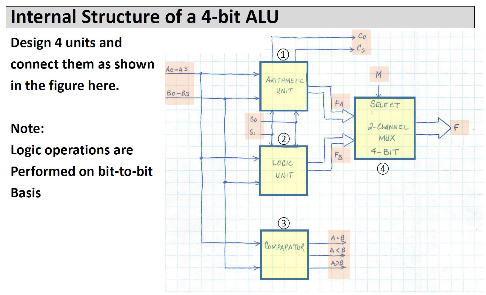
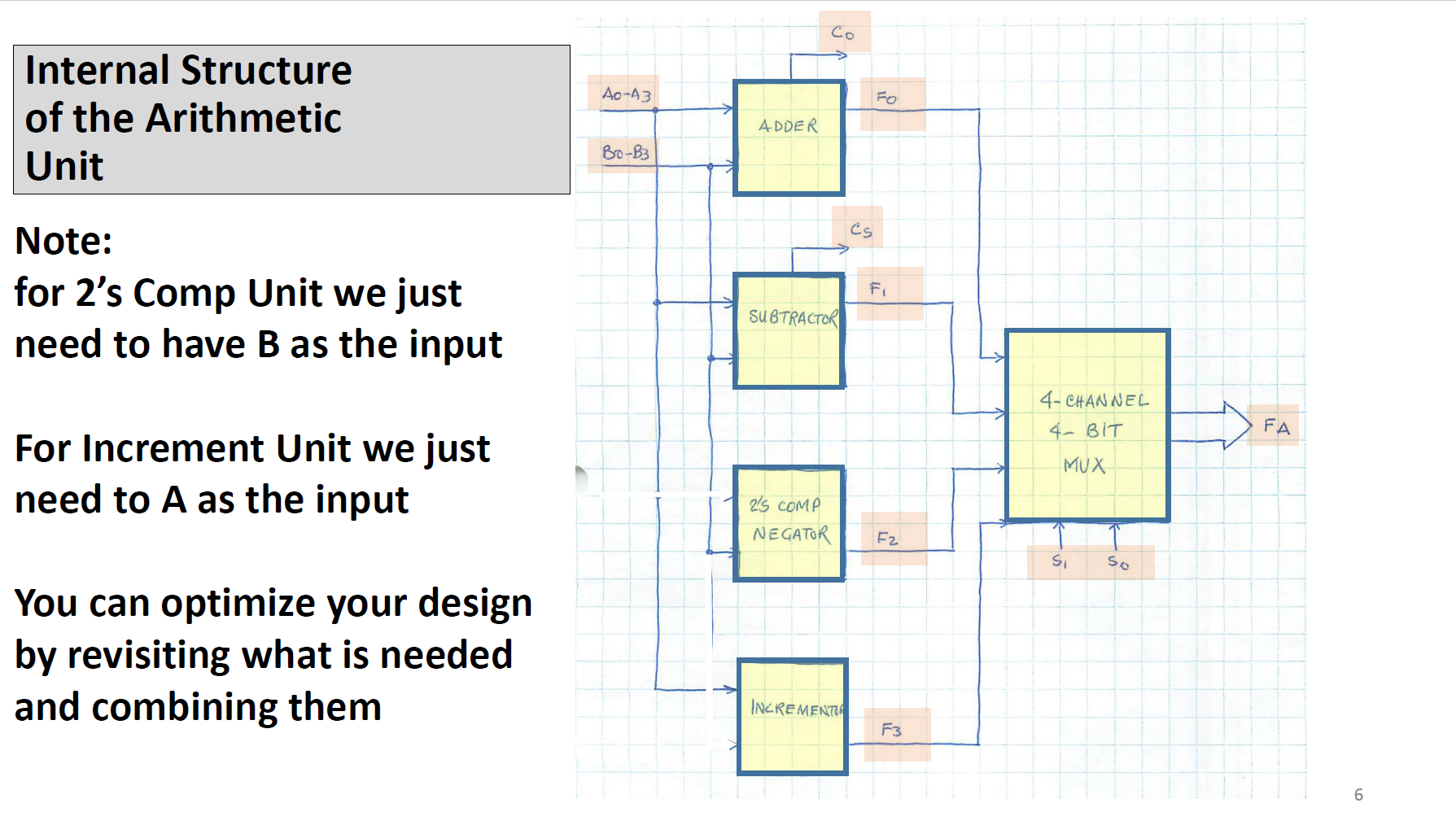
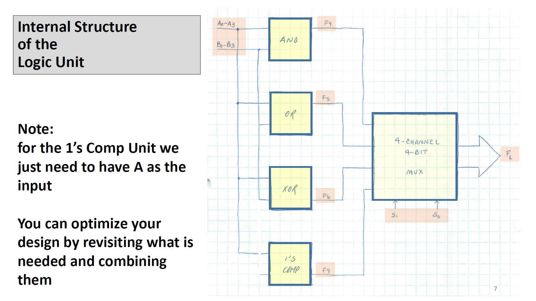
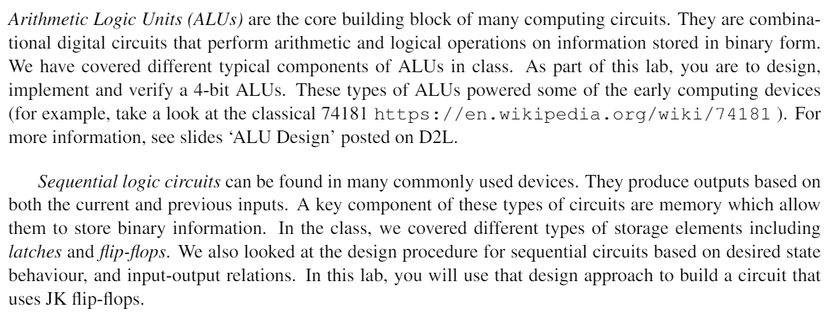
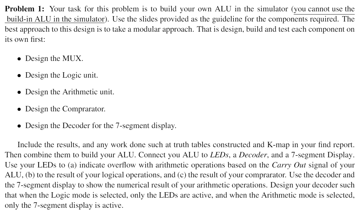
Designing A Simple 4-bit ALU A DATA B Ao A Az A3 Bo B B2 B3 MODE M 4-BIT ALU S So SELECTION Co Cs T F F3 A=B A B } CARRY F (RESULT) COMPARATOR A simple ALU to perform basic 4-bit arithmetic and Logic operations Description A3 A2 A1 A0 B3 B2 B, Ba F3 F2 F Fo 55 is ARE is 4-817 4-BIT INPUTS OUTPUT MODE OF OPERATION ARE SELECT WORKING M=0 Co : CARRY OUT FROM ADDITION The input/output structure A, B and F Other inputs M, S Other outputs C CS: CARRY OUT FROM SUBTRACTION M=1 - ACCORDING ARITHMETIC LOGIC TO T.T. 3 How Mode (M) and Selections (SS) work S 0 0 1 1 Sp 1 0 M = 1 (LOGIC) A: B A+B ABB M=O (ARITHMETIC A PLUS B 4 MINUS B MINUS B (J'S COMPLEMENT) A PLUS I Internal Structure of a 4-bit ALU Design 4 units and connect them as shown in the figure here. Note: Logic operations are Performed on bit-to-bit Basis Ao-A 3 Bo-B3 So S. (1) ARITHMETIC UNIT 2 LOGIC UNIT (3) COMPARATOR FA FB A-B #M A B Co Cs M SELECT 2-CHANNEL 4-BIT 4 F Internal Structure of the Arithmetic Unit Note: for 2's Comp Unit we just need to have B as the input For Increment Unit we just need to A as the input You can optimize your design by revisiting what is needed and combining them Ao-43 Bo-B3 ADDER Co SUBTRACTOR 25 COMP NEGATOR INCREMENT Cs FO F F2 F3 4-CHANNEL 4- BIT MUX S So FA 6 Internal Structure of the Logic Unit Note: for the 1's Comp Unit we just need to have A as the input You can optimize your design by revisiting what is needed and combining them Ao-A3 - AND OR 1'5 COMP F4 F5 FG F7 4-CHANNEL 4-BIT Si MUX So 7 FL Arithmetic Logic Units (ALUs) are the core building block of many computing circuits. They are combina- tional digital circuits that perform arithmetic and logical operations on information stored in binary form. We have covered different typical components of ALUs in class. As part of this lab, you are to design, implement and verify a 4-bit ALUS. These types of ALUS powered some of the early computing devices (for example, take a look at the classical 74181 https://en.wikipedia.org/wiki/74181). For more information, see slides ALU Design' posted on D2L. Sequential logic circuits can be found in many commonly used devices. They produce outputs based on both the current and previous inputs. A key component of these types of circuits are memory which allow them to store binary information. In the class, we covered different types of storage elements including latches and flip-flops. We also looked at the design procedure for sequential circuits based on desired state behaviour, and input-output relations. In this lab, you will use that design approach to build a circuit that uses JK flip-flops. Problem 1: Your task for this problem is to build your own ALU in the simulator (you cannot use the build-in ALU in the simulator). Use the slides provided as the guideline for the components required. The best approach to this design is to take a modular approach. That is design, build and test each component on its own first: Design the MUX. Design the Logic unit. Design the Arithmetic unit. Design the Comprarator. Design the Decoder for the 7-segment display. Include the results, and any work done such at truth tables constructed and K-map in your find report. Then combine them to build your ALU. Connect you ALU to LEDs, a Decoder, and a 7-segment Display. Use your LEDs to (a) indicate overflow with arithmetic operations based on the Carry Out signal of your ALU, (b) to the result of your logical operations, and (c) the result of your comprarator. Use the decoder and the 7-segment display to show the numerical result of your arithmetic operations. Design your decoder such that when the Logic mode is selected, only the LEDs are active, and when the Arithmetic mode is selected, only the 7-segment display is active.
Step by Step Solution
3.50 Rating (157 Votes )
There are 3 Steps involved in it
We know the Excitation table of Sk flip flop Melexia fupil no ... View full answer

Get step-by-step solutions from verified subject matter experts