

Question: pls solve this qus, (embedd system ) For Figure 1, assume that macros named IN_A, IN_B, IN_C and OUT_Y have been defined for RB12, RB13,
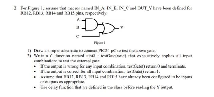
For Figure 1, assume that macros named IN_A, IN_B, IN_C and OUT_Y have been defined for RB12, RB13, RB14 and RB15 pins, respectively. 1) Draw a simple schematic to connect PIC24C to test the above gate. 2) Write a C function named uint8 t testGate(void) that exhaustively applies all input combinations to test the external gate: - If the output is wrong for any input combination, testGate() return 0 and terminate. - If the output is correct for all input combination, testGate() return 1. - Assume that RB12, RB13, RB14 and RB15 have already been configured to be inputs or outputs as appropriate. - Use delay function that we defined in the class before reading the Y output
Step by Step Solution
There are 3 Steps involved in it
To address this problem lets proceed step by step 1 Schematic Drawing You have a digital logic circuit with inputs A B and C connected to a gate and a... View full answer

Get step-by-step solutions from verified subject matter experts