

Question: Power Screw Design Case Study For the C clamp shown below, a force is applied at the end of the 3 8 - in diameter
Power Screw Design Case Study
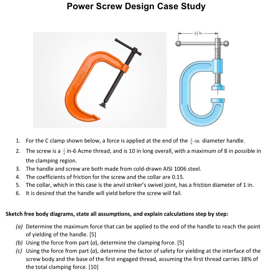
For the C clamp shown below, a force is applied at the end of the in diameter handle.
The screw is a in Acme thread, and is in long overall, with a maximum of in possible in the clamping region.
The handle and screw are both made from colddrawn AISI steel.
The coefficients of friction for the screw and the collar are
The collar, which in this case is the anvil striker's swivel joint, has a friction diameter of in
It is desired that the handle will yield before the screw will fail.
Sketch free body diagrams, state all assumptions, and explain calculations step by step:
a Determine the maximum force that can be applied to the end of the handle to reach the point of yielding of the handle.
b Using the force from part a determine the clamping force.
c Using the force from part a determine the factor of safety for yielding at the interface of the screw body and the base of the first engaged thread, assuming the first thread carries of the total clamping force.
ONLY NEED FREE BODY DIAGRAM DISLIKE IF FBD MISSING
Step by Step Solution
There are 3 Steps involved in it
1 Expert Approved Answer
Step: 1 Unlock

Below is the Free Body Diagram FBD required for the Power Screw Design Case Study specifically addre... View full answer
Question Has Been Solved by an Expert!
Get step-by-step solutions from verified subject matter experts
Step: 2 Unlock
Step: 3 Unlock