

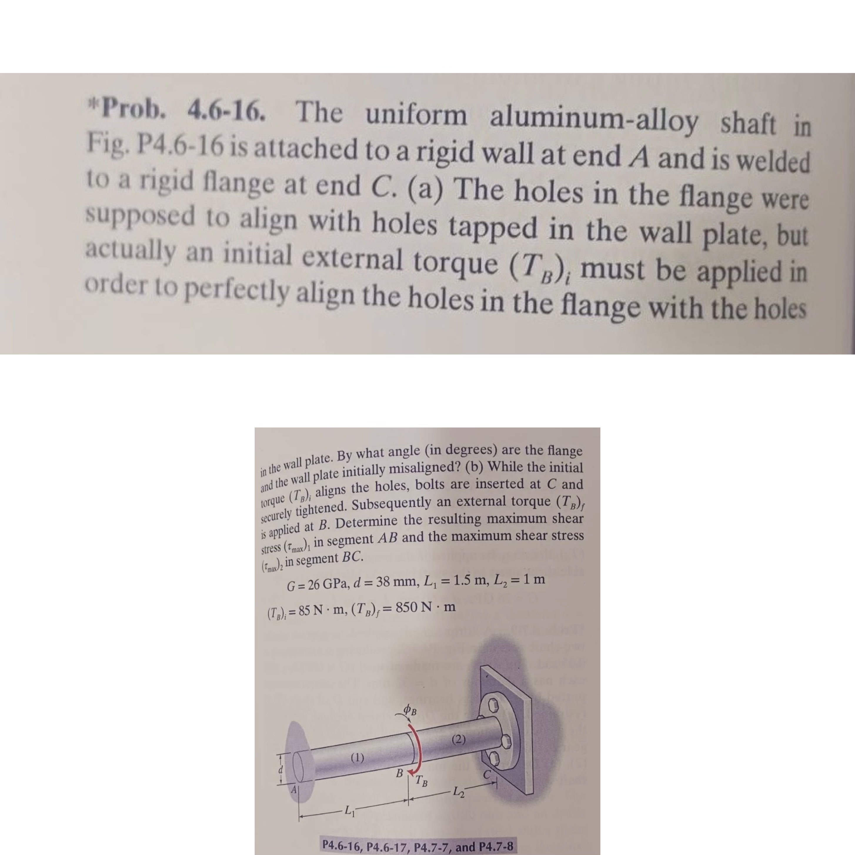
Question: Prob. 4 . 6 - 1 6 . The uniform aluminum - alloy shaft in Fig. P 4 . 6 - 1 6 is attached
"Prob. The uniform aluminumalloy shaft in Fig. P is attached to a rigid wall at end A and is welded to a rigid flange at end a The holes in the flange were supposed to align with holes tapped in the wall plate, but actually an initial external torque must be applied in order to perfectly align the holes in the flange with the holes
Step by Step Solution
There are 3 Steps involved in it
1 Expert Approved Answer
Step: 1 Unlock

Question Has Been Solved by an Expert!
Get step-by-step solutions from verified subject matter experts
Step: 2 Unlock
Step: 3 Unlock