

Question: Heat transfer Multiple pin fins with circular cross sectional Problem # 1: Multiple pin fins with circular cross sectional area Statement of the problem: A
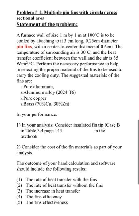
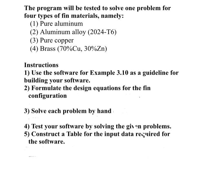
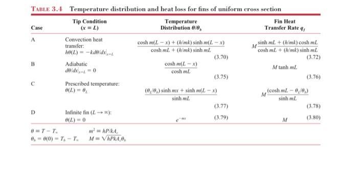
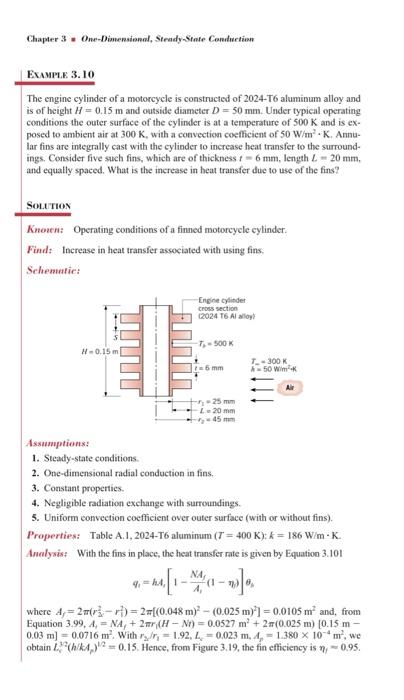
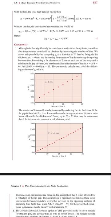
Problem # 1: Multiple pin fins with circular cross sectional area Statement of the problem: A furnace wall of size 1 m by 1 m at 100C is to be cooled by attaching to it 3 cm long, 0.25cm diameter pin fins, with a center-to-center distance of 0.6cm. The temperature of surrounding air is 30C, and the heat transfer coefficient between the wall and the air is 35 W/m.C. Perform the necessary performance to help in selecting the proper material of the fins to be used to carry the cooling duty. The suggested materials of the fins are: 1. Pure aluminum, 2. Aluminum alloy (2024-T6) 3. Pure copper 4. Brass (70%Cu, 30%Zn) In your performance: 1) In your analysis: Consider insulated fin tip (Case B in Table 3.4 page 144 in the textbook. 2) Consider the cost of the fin materials as part of your analysis. The outcome of your hand calculation and software should include the following results: (1) The rate of heat transfer with the fins (2) The rate of heat transfer without the fins (3) The increase in heat transfer (4) The fins efficiency (5) The fins effectiveness The program will be tested to solve one problem for four types of fin materials, namely: (1) Pure aluminum (2) Aluminum alloy (2024-T6) (3) Pure copper (4) Brass (70%Cu, 30%Zn) Instructions 1) Use the software for Example 3.10 as a guideline for building your software. 2) Formulate the design equations for the fin configuration 3) Solve each problem by hand 4) Test your software by solving the given problems. 5) Construct a Table for the input data required for the software. B TABLE 3.4 Temperature distribution and heat loss for fins of uniform cross section Tip Condition Temperature Fin Heat Case (x =) Distribution 0/0 Transfer Rate Convection heat transfer: cosh mL - x) + (h/mk) sinh m(L - x) sinh mL + (hmk) cosh ml ho(L) = - kdo do cosh m + (h/mk) sinh ml cosh mL + (h/mk) sinh mL (3.70) (3.72) Adiabatic cosh m(L-X) de/dx=0 Mtanh ml cosh mL (3.75) (3.76) Prescribed temperature: 0(L) - (6/6, sinh x + sinh m(L - x) (cosh mL - 0,00 sinh L sinh mL (3.77) (3.78) Infinite fin ( 10) (L) - 0 (3.79) M (3.80) 0T-T. APRA 0-00) - T.-T. MVAPRA D Chapter 3 One-Dimensional, Steady-State Conduct duction EXAMPLE 3.10 The engine cylinder of a motorcycle is constructed of 2024-T6 aluminum alloy and is of height 11 = 0.15 m and outside diameter D = 50 mm. Under typical operating conditions the outer surface of the cylinder is at a temperature of 500 K and is ex- posed to ambient air at 300 K, with a convection coefficient of 50 W/m - K. Annu. har fins are integrally cast with the cylinder to increase heat transfer to the surround- ings. Consider five such fins, which are of thickness: - 6 mm, length L - 20mm, and equally spaced. What is the increase in heat transfer due to use of the fins? SOLUTION Known: Operating conditions of a finned motorcycle cylinder. Find: Increase in heat transfer associated with using fins Schematic Engine Cylinder Cross section (2024 T6 All -T-500K -0.15 m 6 mm T-300K 50 Wim 125 mm 120 mm 45 mm Assumptions: 1. Steady-state conditions 2. One-dimensional radial conduction in fins. 3. Constant properties. 4. Negligible radiation exchange with surroundings. 5. Uniform convection coefficient over outer surface with or without fins). Properties: Table A.1, 2024-T6 aluminum (T = 400 K): k = 186 Wim-K. Analysis: With the fins in place, the heat transfer rate is given by Equation 3.101 NA 4. I- 8 where A = 23-r)=2[(0.048 m) - (0.025 m)] = 0.0105 m and, from Equation 3.99, A, = NA, + 2 (H - NO) = 0.0527m' +2(0.025 m) 0.15 m 0.03 m) = 0.0716 m' Withryn = 1.92, 21 -0.023 m, 4,- 1.380 x 10 m, we obtain 2**(hk) = 0.15. Hence, from Figure 3.19, the fin efficiency is 0.95. 3,6 . Went Townsfer from Extended Surferes 157 With the fins, the total heat transfer rate is the 9, 50 W/me-K = 0.9716ml-300 me (0.05) 200 K 690 W 0.0716 Without the fins, the convection heat transfer rate would be 4--2016. - 0 Wim-K 20.025 m 0.15 m200K - 236 W Honde 44-4-454 w Comments: 1. Although the fins significantly increase beat transfer from the cylinder, consider able improvement could still be obtained by increasing the number of fins. We assess this possability by computing 4, as a function of N, first by fixing the fin thickness at T = 6 mm and increasing the number of fins by reducing the spacing between fins. Prescribing a fin clearance of 2 mm at each end of the amay and a minimum tin gap of 4 mm, the maximum allowable number of fins is N-HS- 0.15 m (0.004 + 0.006) m = 15. The parametric calculations yield the follow ing variation of with 1600 1400 mm 1000 200 LS 600 Number of The number of fins could also be increased by reducing the fin thickness. If the fin gap is fixed at (S-1) = 4 mm and manufacturing constraints dictate a mi imum allowable fin thickness of 2mm, up to N-25 fins may be accommo dated. In this case the parametric calculations yield 2500 2000 1100 1000 500 10 20 25 NN Chapter 3 On-Dimensional, SteadyState Conduction The foregoing calculations are based on the assumption that is not affected by a reduction in the fin gap. The assumption is reasonable as long as there is no interaction between boundary layers that develop on the opposing surfaces of adjoining fins. Note that, since MA, 2-NI) for the prescribed.com tions, increases nearly linearly with increasing 2. The Models Extended Surfaces option of IT provides ready-to-solve models for straight, pin, and circular fins, as well as for fin arays. The models include har111 TL 15
Step by Step Solution
There are 3 Steps involved in it

Get step-by-step solutions from verified subject matter experts