

Question: Problem 1 A rotary encoder has two outputs, a pulsed signal (P, 50% duty cycle) with a period corresponding to angular velocity, and a directional
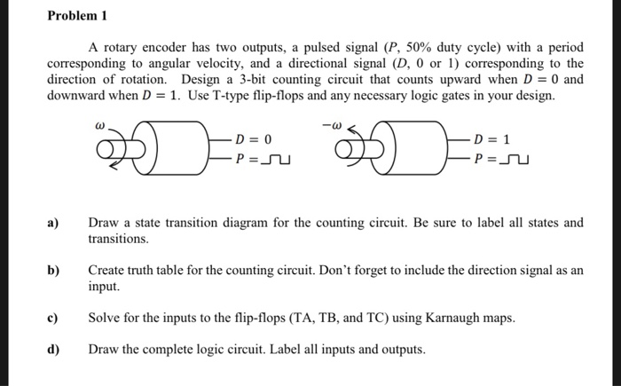
Problem 1 A rotary encoder has two outputs, a pulsed signal (P, 50% duty cycle) with a period corresponding to angular velocity, and a directional signal (D, 0 or 1) corresponding to the direction of rotation. Design a 3-bit counting circuit that counts upward when D0 and downward when D 1. Use T-type flip-flops and any necessary logic gates in your design. )-1 P-u a) Drw a state transition diagram for the counting circuit. Be sure to label all states and b) Create truth table for the counting circuit. Don't forget to include the direction signal as an c Solve for the inputs to the flip-flops (TA, TB, and TC) using Karnaugh maps transitions input d) Draw the complete logic circuit. Label all inputs and outputs
Step by Step Solution
There are 3 Steps involved in it

Get step-by-step solutions from verified subject matter experts