

Question: Problem 1 : B . JT DC Circuits. Let the NPN BJT QN have the following properties: { V B E N = 0 .
Problem : BJT DC Circuits.
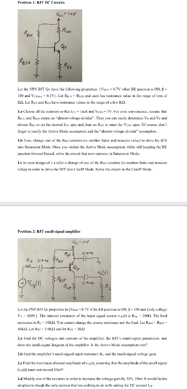
Let the NPN BJT QN have the following properties: when BE junction is and : Let and each has resistance value in the range of tens of Lel Ren and Ren have resistance values in the range of a lew
a Choose all the resistors so that and For your convenience, assume that and creale an "almostvoltagedivider". Then you can easily delermine and and chouse to set the desired spee and then set to meet the spee. Of course, don't forget to justify the Active Mode assumption and the "almostvoltagedivider" assumption.
b Now, change one of the resistors to another finite and nonzero value to drive the BJT into Saturation Mode. Once you violate the Active Mode assumption, while still keeping the BE junction forward biased, solve the circuit that now operates in Saturation Mode.
e In your design of a offer a change of one of the resistors to another finite and nonzero value in order to drive the BIT into Cutoff Mode. Solve the circuit in the Cutoff Mode.
Problem : BJT smallsignal amplifier.
Let the properties be if the EB junction is and Early voltage ; The internal resistance of the input signal source is The load resistance is You cannot change the source resistance nor the load. Let Let and let
a Find the DC voltages and currents of the amplifier, the BJTs smallsignal parameters, and draw the smallsignal diagram of the amplifier. Is the Active Mode assumption true?
b Find the amplifier's smallsignal input resistance and the smallsignal voltage gain.
c Find the maximum allowed amplitude of assuming that the amplitude of the small signal must not exceed mV
d Modify one of the resistors in order to increase the voltage gain by Hint: It would be the simplest to tweak the only resistor that has nothing to do with setting the DC current
Step by Step Solution
There are 3 Steps involved in it
1 Expert Approved Answer
Step: 1 Unlock

Question Has Been Solved by an Expert!
Get step-by-step solutions from verified subject matter experts
Step: 2 Unlock
Step: 3 Unlock